56
Super X13DAI-T User's Manual
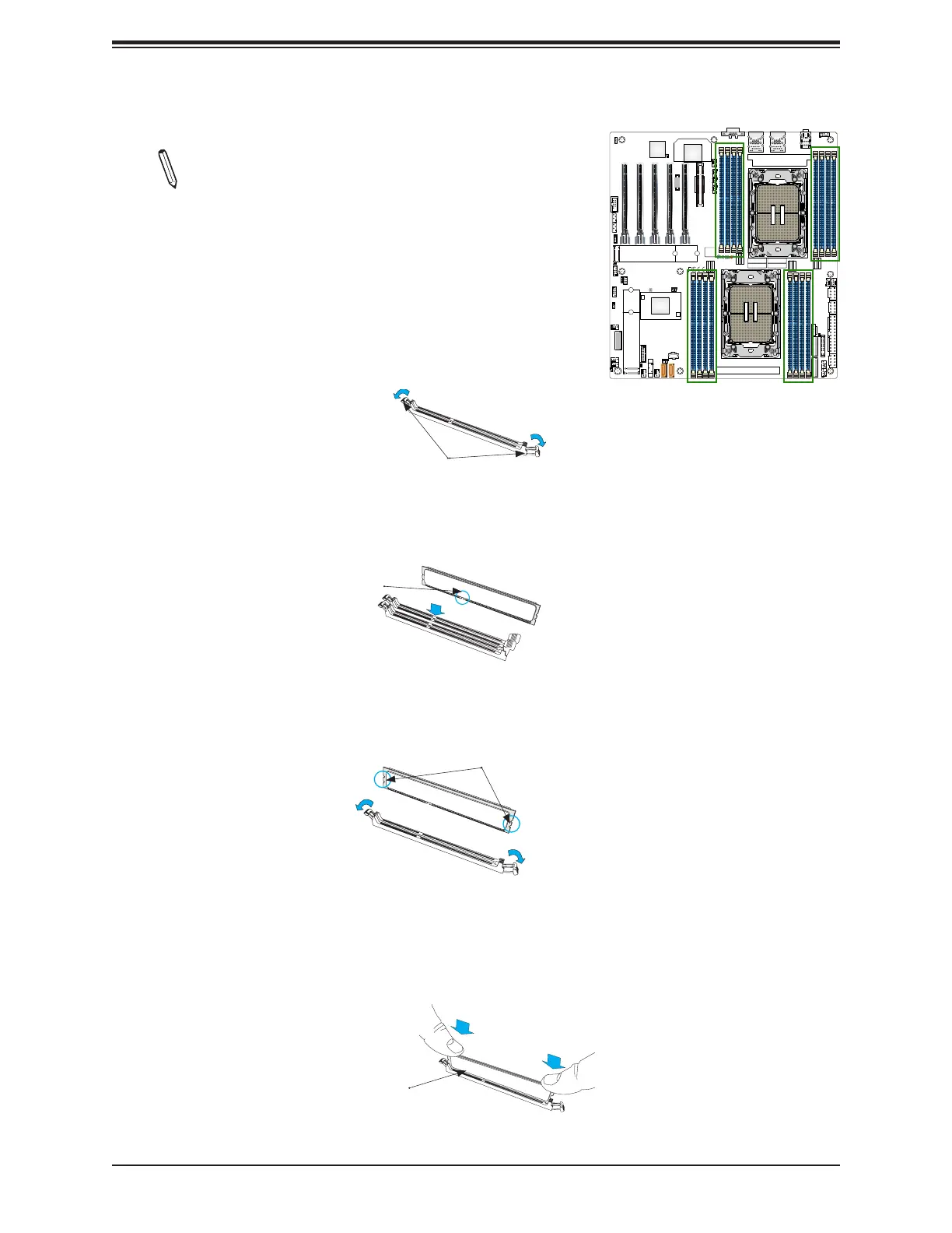
DIMM Installation
Note: The DDR5 DIMM module is NOT hot-swappable
and be sure to disconnect power for a minimum of
twenty seconds before inserting or removing it.
1. Insert the desired number of DIMMs into the memory
slots based on the recommended DIMM population tables
in the previous section. Locate DIMM memory slots on
the motherboard as shown on the right.
2. Push the release tabs outwards on both ends of the
DIMM slot to unlock it.
Release Tabs
Push both ends
straight down into
the memory slot.
3. Align the key of the memory module with the receptive point on the memory slot.
Key
4. Align the notches on both ends of the module against the receptive points on the ends
of the slot.
5. Push both ends of the module straight down into the slot until the module snaps into
place.
6. Press the release tabs to the lock positions to secure the memory module into the slot.
Notches
CPU2
CPU1
DESIGNED IN USA
MAC CODE
IPMI CODE
BAR CODE
CM CODE
X13DAI-T
REV:1.00
BIOS
LICENSE
BT1
MH13
MH12
MH11MH10
JAUDIO1
T-SGPIO1
JPI2C1
JNCSI1
JSD2JSD1
JBT1
JS1
LEDBMC1
LED4
LED7
LEDPWR1
JF1
JPWR1
JPWR3
JPWR2
JNVI2C1
JIPMB1
JPG1
JTP1
JPTG1
JL1
JVRM1
JVRM2
JTPM1
JRK1
FANC
FAN6
FAN7
FAN5
FAN8
FAN9
FANB
FANA
FAN1
FAN2
FAN3
FAN4
LAN
CTRL
AUDIO FP
USB8 (3.1 Gen 2)
P1_NVME0/1
P2_NVME0/1
(NVME ONLY)
M.2-C1
(PWR I2C)
COM1
(SATA0~7)
I-SATA9
I-SATA8
USB0/1
(CLEAR CMOS)
USB6/7 (3.0)
P1-DIMMF1
P1-DIMME1
P1-DIMMH1
P1-DIMMG1
P2-DIMMD1
P2-DIMMB1
P2-DIMMA1
P2-DIMMC1
P1-DIMMB1
P1-DIMMA1
P1-DIMMD1
P1-DIMMC1
P2-DIMMG1
P2-DIMMH1
P2-DIMME1
P2-DIMMF1
VGA
(JPCIE1) P1 SLOT1 PCIe 5.0 x16
(JPCIE2)
P2 SLOT2 PCIe 5.0 x16
(JPCIE3)
P1 SLOT3 PCIe 5.0 x16
(JPCIE4)
P2 SLOT4 PCIe 5.0 x16
(JPCIE6)
P2 SLOT6 PCIe 5.0 x8
(JPCIE5)
P1 SLOT5 PCIe 5.0 x16
BMC
(NVME ONLY)
M.2-C2
PCH
USB2/3 (3.0)
LAN1
USB4/5 (3.0)
LAN2
 Loading...


