71
Chapter 2: Installation
1. Power LED
2. M.2-C01 LED
3. M.2-C02 LED
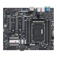
Onboard Power LED
The Onboard Power LED is located at Power LED on the motherboard. When this LED is on,
the system is on. Be sure to turn o the system and unplug the power cord before removing
or installing any component. Refer to the table below for more information.
Onboard Power LED Indicator
LED Color Denition
O
System O (power cable
not connected)
Green System On
M.2 LEDs
Two M.2 LEDs are located at M.2-C01 LED and M.2-C02 LED on the motherboard. When the
M.2 LED is blinking, M.2 functions normally. Refer to the table below for more information.
M.2 LED State
LED Color Denition
Green: Blinking Device Working
BAR CODE
BAR CODE
IPMI CODE
MAC CODE
MAC CODE
SAS CODE
JTPM1
SP1
USB9 (3.2)
(USB3.2 GEN2X2)
UID-LED
JPI2C1
M.2-C01 LED
M.2-C02 LED
JF1
JWD1
JPL1
JPUSB1
JPL2
JSD1
FAN2
HD AUDIO
AUDIO FP
JUIDB1
LED8
COM1
USB0/1
FANB
FANC
BATTERY
DIMME2
DIMMF2
DIMMF1
DIMME1
DIMMA2
DIMMA1
DIMMB2
DIMMB1
SATA 1
SATA 0
SATA 3
SATA 2
SATA 4
SATA 5
M.2-C01
M.2-C02
JPME2
JL1
JRK1
(RAID Key Header)
JCMOS
JBT1
JPW2
JPW3
FAN1
FANA
JSTBY1
CPU SLOT6 PCIe 5.0 X16
JOH1
JPW1
12V_
PUMP_PWR1
USB8
(USB3.2 GEN2X2)
VGA
CPU SLOT4 PCIe 5.0 X16
PCH SLOT1 PCIe 4.0 X4
CPU SLOT2 PCIe 5.0 X16
BMC LED
JSPDIF_OUT
JPAC1
CPU
PCH
BIOS LICENSE
LAN
CTRL
BMC
USB6/7
(USB3.2 GEN2)
LAN1
USB4/5
(USB3.2 GEN2)
LAN2
Power LED
(PCIe 5.0 X4)
(PCIe 5.0 X4)
X13SRA-TF
DESIGNED IN USA
REV:1.01
JD1
(SPEAKER 1-4)
USB2/3 (3.0)
(USB3.2 GEN1)
LAN
CTRL
2
1
3
 Loading...
