C-4
SC847 Chassis Manual
C-6 Front Connector and Pin Denitions
#2. MG9071 and MG9072 Chips
The MG9071 and MG9072 are enclosure
management chips that support the SES-2
controller and SES-2 protocols.
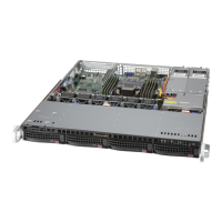
SAS Activity LED Header
Pin Denitions
Pin # Denition Pin # Denition
1 ACT IN#0 6 ACT IN#4
2 ACT IN#1 7 ACT IN#5
3 ACT IN#2 8 ACT IN#6
4 ACT IN#3 9 ACT IN#7
5 Ground 10 Empty
#1. Activity LED Headers
The activity LED headers, designated JP26
and JP47, are used to indicate the activity
status of each SAS drive. The activity LED
headers are located on the front panel. For the
activity lead headers to work properly, connect
to them using a 10-pin LED cable. This is only
used when the activity LED is not supported
by the hard drive.
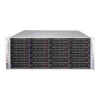
SAS Activity LED Header
Pin Denitions
Pin # Denition Pin # Denition
1 ACT IN#8 6 ACT IN#12
2 ACT IN#9 7 ACT IN#13
3 ACT IN#10 8 ACT IN#14
4 ACT IN#11 9 ACT IN#15
5 Ground 10 Empty
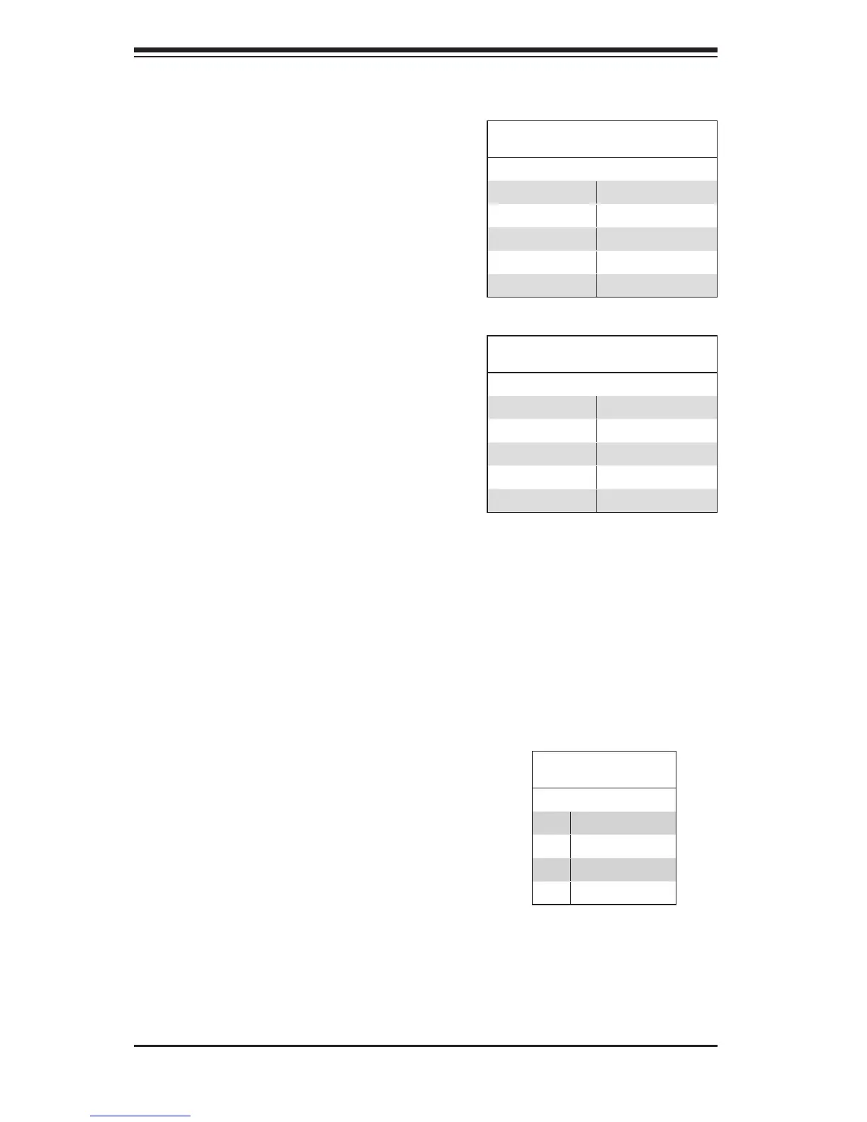
#3., #4., #5. I
2
C Connectors
The I
2
C connectors, designated JP37, JP52,
and JP95, are used to communicate to HDD
to support SES-2 protocol. See the table on the
right for pin denitions.
I
2
C Connector
Pin Denitions
Pin# Denition
1 Data
2 Ground
3 Clock
4 No Connection
 Loading...