D-4
SC847 Chassis Manual
D-6 Front Connector and Pin Denitions
1. MG9072 Chip
The MG9072 is an enclosure management
chip that supports the SES-2 controller and
SES-2 protocols.
2. Upgrade Connectors
The upgrade connectors are designated JP69,
JP78, and JP115 and are used for manufactur-
er's diagnostic purposes only.
3. Activity LED Header
The activity LED header, designated JP26,
JP47 and JP108, is used to indicate the activ-
ity status of each SAS drive. The Activity LED
Header is located on the front panel. For the
Activity LED Header to work properly, connect
using a 10-pin LED cable.
4., 5., 6. I
2
C Connectors
The I
2
C Connectors, designated JP37, JP95,
JP52, JP96, JP116, and JP117, are used
to communicate to HDD to support SES-2
protocol. See the table on the right for pin
denitions.
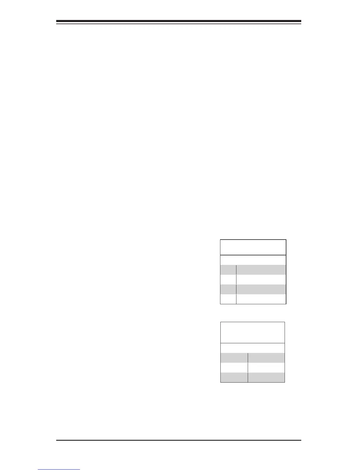
I
2
C Connector
Pin Denitions
Pin# Denition
1 Data
2 Ground
3 Clock
4 No Connection
Backplane
Main Power
4-Pin Connector
Pin# Denition
1
+12V
2 and 3 Ground
4 +5V
7. Backplane Main Power Connectors
The 4-pin connectors, designated JP10, JP13,
JP46, JP48, JP109, and JP110, provide power
to the backplane. See the table on the right for
pin denitions.
 Loading...