Chapter 2: Installation
2-17
Power Button
Unit ID LED
1
NIC1 LED
Reset Button
2
Power Fail LED
HDD LED
Power LED
#3~4
#1~2
Vcc
Vcc
Vcc
OH/Fan Fail
Ground
Ground
1920
Vcc
X
Ground
NMI
X
Vcc
NIC2 LED
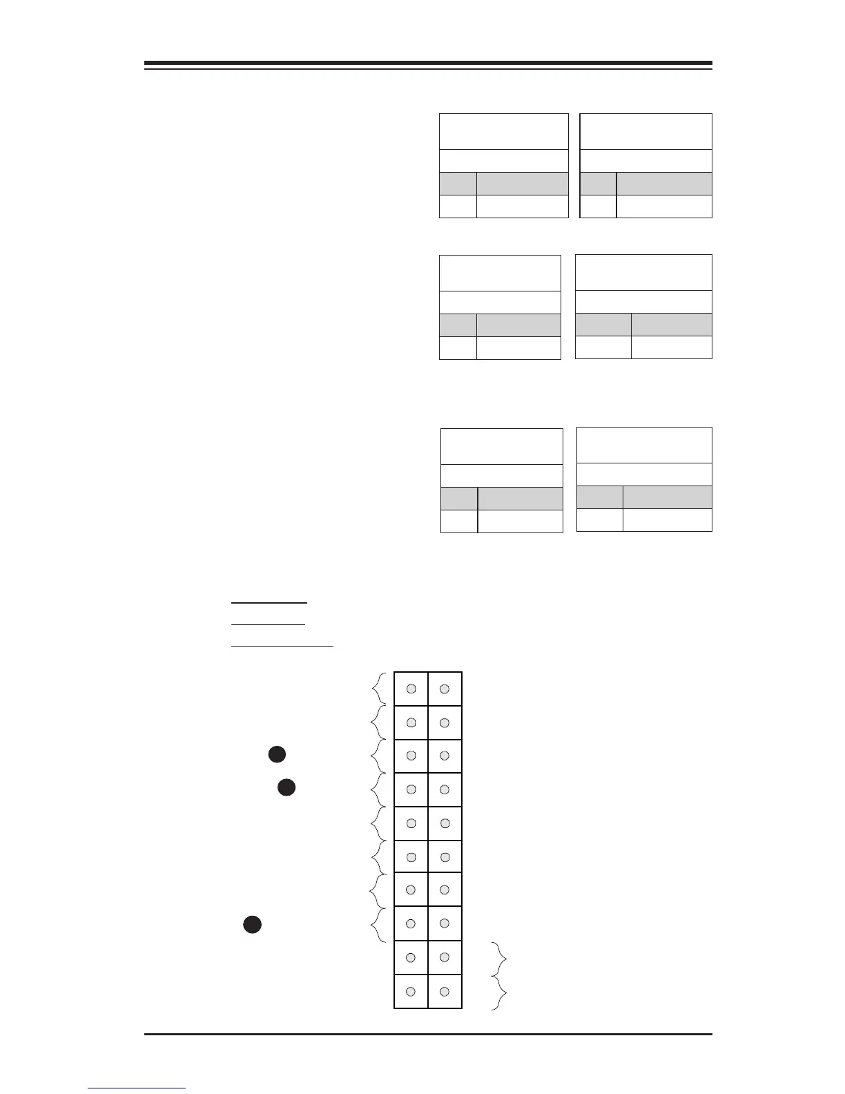
Front Control Panel Pin Denitions
Power LED
The Power LED connection is located
on pins 15 and 16 of JF1. Refer to the
table on the right for pin denitions.
Power LED
Pin Denitions (JF1)
Pin# Denition
15 +5V
16 Ground
A. PWR LED
B. HDD LED
C. PWR Fail LED
A
B
HDD LED
The HDD LED connection is located
on pins 13 and 14 of JF1. Attach a
cable here to indicate the status of
HDD-related activities, including IDE,
SATA activities. See the table on the
right for pin denitions.
HDD LED
Pin Denitions (JF1)
Pin# Denition
13 +5V
14 HD Active
Power Fail LED
The Power Fail LED connection is
located on pins 5 and 6 of JF1. Refer
to the table on the right for pin deni-
tions.
PWR Fail LED
Pin Denitions (JF1)
Pin# Denition
5 Vcc
6 Ground
C
Power LED
Status
State Denition
Off System Off
On System Running
HDD LED
Status
State Denition
Off No Activity
Blinking HDD Busy
Power Fail LED
Status
State Denition
Off Normal
On Power Failure

 Loading...


