Chapter 2: Installation
2-29
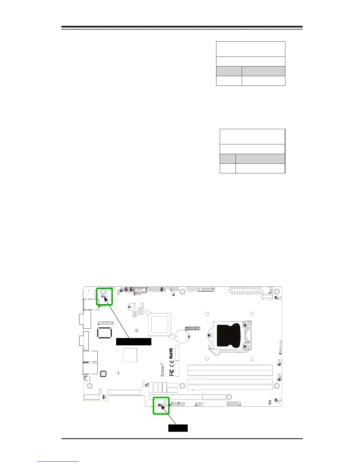
BMC Enable/Disable (JPB)
JPB is used to enable or disable
the BMC (Baseboard Management
Control) chip and the onboard IPMI
port. This jumper is used together with
the IPMI settings in the BIOS. See
the table on the right for the jumper
settings.
BMC IPMI Enable/Disable
(JPB) Jumper Settings
Setting Denition
Pins 1-2 Enabled (Default)
Pins 2-3 Disabled
MAC CODE
BAR CODE
JSD1
1
3
JF1
20
LE5
A
C
C768
J28
JPW2
R137
RT1
COM1
JI2C1
1
JI2C2
1
J29
1
JPME1
JPME2
JL1
7
JLAN2
JLAN1
T-SGPIO1
T-SGPIO2
+
SPKR1
J31
J15
CA
LE7
LE2
A
C
LE3
A
C
LE4
A
C
J16
JTPM
B1
+
JBT1
1
4
J5
JSPK
JPI2C
JPW1
1
SW1
1
JSTBY1
1
3
JUSB4
JUSB3
1
10
11
J1
MH8
MH4
MH3
MH7
MH2
MH5 MH6
JRF1
13
1
JPL1
1
JPL2
JLED
JWD
JPUSB1
JPB
JPG1
1
3
J8
J4
4
FAN5
FAN3
FAN1
FAN2
FAN4
J3
J2
CPU
JRF1
2-3:FORCE TO X8+X8
1-2:AUTO
Buzzer/Speaker
JWD
2-3:NMI
1-2:RST
USB 3.0-0/1
SBX3: PCI-E 2.0 X4
NMI
X
ON:ME RECOVERY
JPME1
OFF:NORMAL
JPME2
OFF:NORMAL
ON:ME MANUFACTURING MODE
USB3.0-2/3
REV:1.00
X9SPU-F
JPUSB1
2-3:DISABLE
1-2:ENABLE
JPUSB1:B/P USB WAKE UP
JSPK:
JPI2C:PWR I2C
JLED:Power LED
OH/FF
COM2
JI2C1/JI2C2
OFF:Disable
ON:Enable
2-3:DISABLE
1-2:ENABLE
JPB:BMC
GND GND 5V
SBX1: PCI-E 3.0/2.0 X16 or X8+X8
DDR3 1600/1333/1066 UDIMM/RDIMM required
I-SATA0
I-SATA1
JSD1:DOM_PWR
SBX2: PCI-E 2.0 X4 in X8
UIOP
UID-LED
USB4/5/IPMI_LAN
I-SATA2
I-SATA3
I-SATA4
JF1
DIMMA2
DIMMA1
DIMMB1
DIMMB2
DESIGNED IN USA
2-3:DISABLE
1-2:ENABLE
JPL2 LAN2
LED
PF
KB/MS
RST
PWR ON
1
NIC
UID
2
PS
FAIL LED
PWR
HDD
1
NIC
COM1
SPEAKER
LAN1
VGA
LAN2
2-3:DISABLE
1-2:ENABLE
JPG1 VGA
CMOS CLEAR
1-2:ENABLE
2-3:DISABLE
JPL1 LAN1
USB 12/13
I-SATA5
JL1:CHASSIS INSTRUSION
JPB
USB Wake-Up (JPUSB1)
Use the jumper JPUSB1 to "wake-up"
your system by pressing a key on a
USB keyboard or clicking the USB
mouse connected to the backpanel
USB Ports 4/5. JPUSB1 is used to-
gether with a USB Wake-Up feature in
the BIOS. Enable this jumper and the
USB support in the BIOS to wake up
your system via USB devices.
Note: When the USB is set to
Enabled in the BIOS, and JPUSB1
is set to Disabled, remove the USB
devices from backpanel USB Ports
0/1 before the system goes into
the standby mode.
JPUSB1 (Backplane USB
0/1 Wake-up Enable)
Pin# Denition
1-2 Enabled (Default)
2-3 Disabled
JPUSB1

 Loading...


