Chapter 2: Installation
2-19
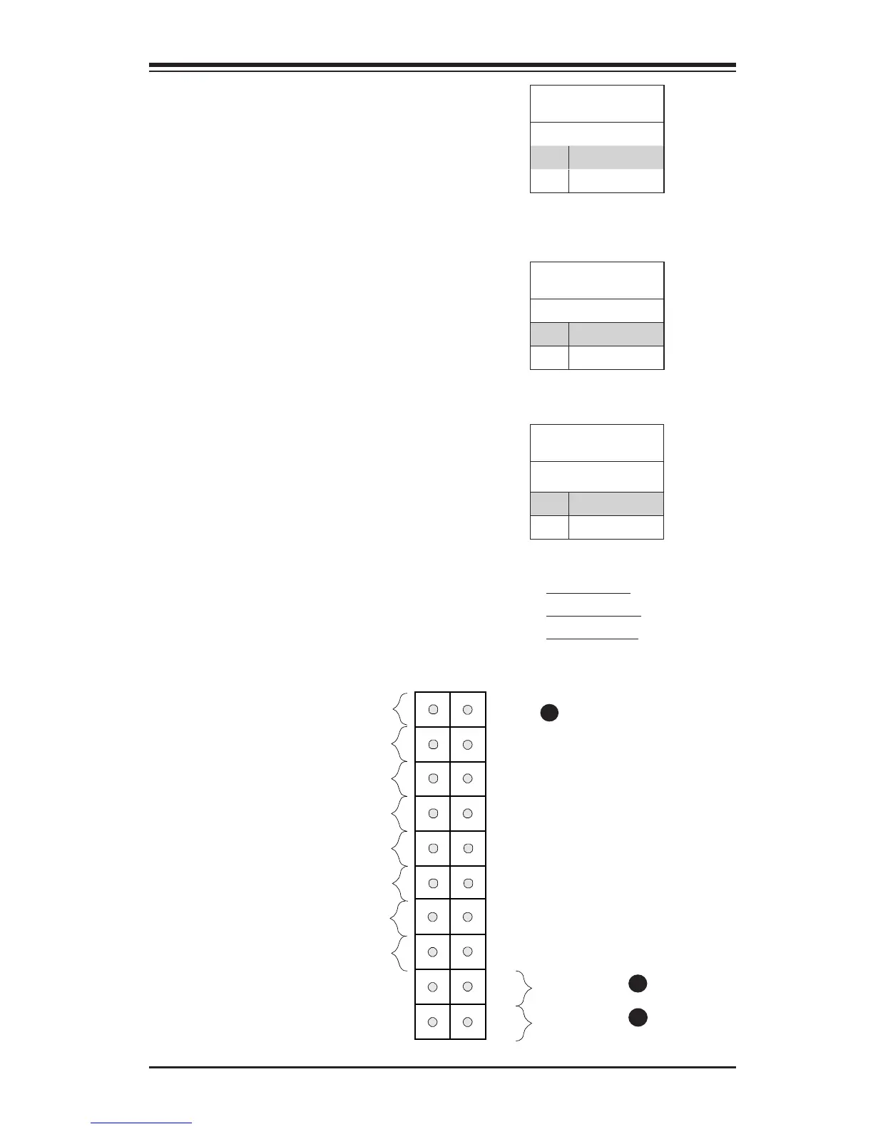
NMI Button
The non-maskable interrupt button
header is located on pins 19 and 20
of JF1. Refer to the table on the right
for pin denitions.
NMI Button
Pin Denitions (JF1)
Pin# Denition
19 Control
20 Ground
Power Button
The Power Button connection is locat-
ed on pins1 and 2 of JF1. Momentarily
contacting both pins will power on/off
the system. This button can also be
congured to function as a suspend
button (with a setting in the BIOS - see
Chapter 4). To turn off the power in the
suspend mode, press the button for at
least 4 seconds. Refer to the table on
the right for pin denitions.
Power Button
Pin Denitions (JF1)
Pin# Denition
1 Signal
2 +3V Standby
Reset Button
The Reset Button connection is lo-
cated on pins 3 and 4 of JF1. Momen-
tarily contacting both pins will hard re-
set the system. Attach it to a hardware
reset switch on the computer case to
reset the system. Refer to the table on
the right for pin denitions.
Reset Button
Pin Denitions (JF1)
Pin# Denition
3 Reset
4 Ground
A. NMI Button
B. Reset Button
C. PWR Button
A
B
Power Button
Unit ID LED
1
NIC1 LED
Reset Button
2
Power Fail LED
HDD LED
Power LED
#3~4
#1~2
Vcc
Vcc
Vcc
OH/Fan Fail
Ground
Ground
1920
Vcc
X
Ground
NMI
X
Vcc
NIC2 LED
C
 Loading...


