2-22
X9SPU-F Motherboard User’s Manual
MAC CODE
BAR CODE
JSD1
1
3
JF1
20
LE5
A
C
C768
J28
JPW2
R137
RT1
COM1
JI2C1
1
JI2C2
1
J29
1
JPME1
JPME2
JL1
7
JLAN2
JLAN1
T-SGPIO1
T-SGPIO2
+
SPKR1
J31
J15
CA
LE7
LE2
A
C
LE3
A
C
LE4
A
C
J16
JTPM
B1
+
JBT1
1
4
J5
JSPK
JPI2C
JPW1
1
SW1
1
JSTBY1
1
3
JUSB4
JUSB3
1
10
11
J1
MH8
MH4
MH3
MH7
MH2
MH5 MH6
JRF1
13
1
JPL1
1
JPL2
JLED
JWD
JPUSB1
JPB
JPG1
1
3
J8
J4
4
FAN5
FAN3
FAN1
FAN2
FAN4
J3
J2
CPU
JRF1
2-3:FORCE TO X8+X8
1-2:AUTO
Buzzer/Speaker
JWD
2-3:NMI
1-2:RST
USB 3.0-0/1
SBX3: PCI-E 2.0 X4
NMI
X
ON:ME RECOVERY
JPME1
OFF:NORMAL
JPME2
OFF:NORMAL
ON:ME MANUFACTURING MODE
USB3.0-2/3
REV:1.00
X9SPU-F
JPUSB1
2-3:DISABLE
1-2:ENABLE
JPUSB1:B/P USB WAKE UP
JSPK:
JPI2C:PWR I2C
JLED:Power LED
OH/FF
COM2
JI2C1/JI2C2
OFF:Disable
ON:Enable
2-3:DISABLE
1-2:ENABLE
JPB:BMC
GND GND 5V
SBX1: PCI-E 3.0/2.0 X16 or X8+X8
DDR3 1600/1333/1066 UDIMM/RDIMM required
I-SATA0
I-SATA1
JSD1:DOM_PWR
SBX2: PCI-E 2.0 X4 in X8
UIOP
UID-LED
USB4/5/IPMI_LAN
I-SATA2
I-SATA3
I-SATA4
JF1
DIMMA2
DIMMA1
DIMMB1
DIMMB2
DESIGNED IN USA
2-3:DISABLE
1-2:ENABLE
JPL2 LAN2
LED
PF
KB/MS
RST
PWR ON
1
NIC
UID
2
PS
FAIL LED
PWR
HDD
1
NIC
COM1
SPEAKER
LAN1
VGA
LAN2
2-3:DISABLE
1-2:ENABLE
JPG1 VGA
CMOS CLEAR
1-2:ENABLE
2-3:DISABLE
JPL1 LAN1
USB 12/13
I-SATA5
JL1:CHASSIS INSTRUSION
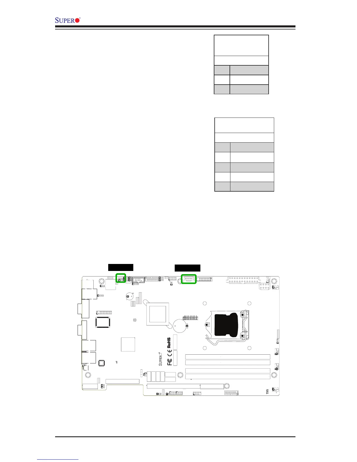
Legacy Wake-On-LAN Header
(JSTBY1)
The onboard LANs (LAN1 and LAN2)
do not need WOL header to support
its Wake-On-LAN function. We
preserved the legacy WOL header
to provide convenience for some
embedded customers who need in-
ternal power source from the board.
See the table on the right for pin
denitions.
Wake-On-LAN
(JSTBY1)
Pin Denitions
Pin# Denition
1 +5V Standby
2 Ground
3 Wake-up
Power Supply I2C (JPI2C2)
The Power Supply I2C Connector,
located at JI2C1, monitors the status
of the power supply, fan and system
temperature. See the table on the right
for pin denitions.
PWR Supply (I2C)
Pin Denitions
Pin# Denition
1 Clock
2 Data
3 PWR Fail
4 Ground
5 3.3V
JSTBY1
JPI2C2

 Loading...


