2-26
X9SPU-F Motherboard User’s Manual
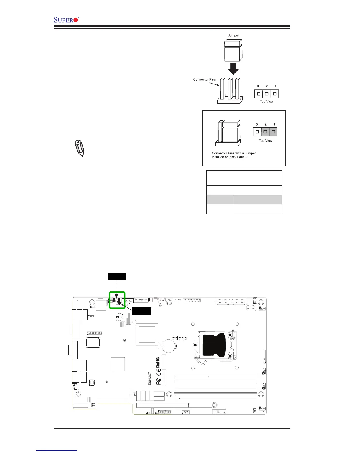
2-7 Jumper Settings
Explanation of Jumpers
To modify the operation of the mother-
board, jumpers can be used to choose
between optional settings. Jumpers
create shorts between two pins to
change the function of the connector.
Pin 1 is identied with a square solder
pad on the printed circuit board.
Note: On two pin jumpers,
"Closed" means the jumper
is on, and "Open" means the
jumper is off the pins.
LAN Port Enable/Disable (JPL1/
JPL2)
Jumpers JPL1 and JPL2 enables or
disables LAN Port 1 and LAN Port 2
on the motherboard. See the table
on the right for jumper settings. The
default setting is enabled.
MAC CODE
BAR CODE
JSD1
1
3
JF1
20
LE5
A
C
C768
J28
JPW2
R137
RT1
COM1
JI2C1
1
JI2C2
1
J29
1
JPME1
JPME2
JL1
7
JLAN2
JLAN1
T-SGPIO1
T-SGPIO2
+
SPKR1
J31
J15
CA
LE7
LE2
A
C
LE3
A
C
LE4
A
C
J16
JTPM
B1
+
JBT1
1
4
J5
JSPK
JPI2C
JPW1
1
SW1
1
JSTBY1
1
3
JUSB4
JUSB3
1
10
11
J1
MH8
MH4
MH3
MH7
MH2
MH5 MH6
JRF1
13
1
JPL1
1
JPL2
JLED
JWD
JPUSB1
JPB
JPG1
1
3
J8
J4
4
FAN5
FAN3
FAN1
FAN2
FAN4
J3
J2
CPU
JRF1
2-3:FORCE TO X8+X8
1-2:AUTO
Buzzer/Speaker
JWD
2-3:NMI
1-2:RST
USB 3.0-0/1
SBX3: PCI-E 2.0 X4
NMI
X
ON:ME RECOVERY
JPME1
OFF:NORMAL
JPME2
OFF:NORMAL
ON:ME MANUFACTURING MODE
USB3.0-2/3
REV:1.00
X9SPU-F
JPUSB1
2-3:DISABLE
1-2:ENABLE
JPUSB1:B/P USB WAKE UP
JSPK:
JPI2C:PWR I2C
JLED:Power LED
OH/FF
COM2
JI2C1/JI2C2
OFF:Disable
ON:Enable
2-3:DISABLE
1-2:ENABLE
JPB:BMC
GND GND 5V
SBX1: PCI-E 3.0/2.0 X16 or X8+X8
DDR3 1600/1333/1066 UDIMM/RDIMM required
I-SATA0
I-SATA1
JSD1:DOM_PWR
SBX2: PCI-E 2.0 X4 in X8
UIOP
UID-LED
USB4/5/IPMI_LAN
I-SATA2
I-SATA3
I-SATA4
JF1
DIMMA2
DIMMA1
DIMMB1
DIMMB2
DESIGNED IN USA
2-3:DISABLE
1-2:ENABLE
JPL2 LAN2
LED
PF
KB/MS
RST
PWR ON
1
NIC
UID
2
PS
FAIL LED
PWR
HDD
1
NIC
COM1
SPEAKER
LAN1
VGA
LAN2
2-3:DISABLE
1-2:ENABLE
JPG1 VGA
CMOS CLEAR
1-2:ENABLE
2-3:DISABLE
JPL1 LAN1
USB 12/13
I-SATA5
JL1:CHASSIS INSTRUSION
JPL2
JPL1
Speaker Connector
Pin Denitions
Pin Setting Denition
Pins 3~4 Internal Speaker
Pins1~4 External Speaker

 Loading...


