Do you have a question about the Supmeter BST106-N59 and is the answer not in the manual?
Covers battery, environment, installation, sensors, cabling, and disposal guidelines for safe operation and maintenance.
Explains how the wheel loader weigher functions dynamically, using sensors and processing for weighing.
Lists the components included in the weighing system, such as indicator, sensors, and joints.
Specifies the range of wheel loaders suitable for the weighing system based on capacity.
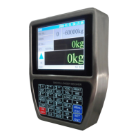
Details display, keypad, sensor interfaces, and communication ports of the weighing indicator.
Outlines operating voltage, detecting distance, frequency, and protection levels of the position sensor.
Provides details on operating voltage, capacity, accuracy, sensitivity, and temperature range of the oil pressure sensor.
Specifies accuracy grades for the weighing indicator, single-bucket, and totalized loading weight.
Describes the layout and elements of the primary display screen of the weighing indicator.
Explains keypad functions for modes, menu navigation, parameter setting, calibration, and loading process operations.
Covers the physical installation process of the weighing system components on the wheel loader.
Identifies key parts of the wheel loader relevant to the installation.
Provides instructions for securely mounting the weighing indicator unit in the cab.
Details the assembly and mounting of the position sensor modules and magnet block.
Guides on positioning, safety, and connecting the oil pressure sensors and joints.
Advises on properly routing and protecting sensor signal cables.
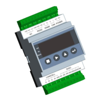
Illustrates the terminal layout and connector types on the weighing indicator.
Explains the wiring and connection procedures for system components.
Explains the pin configuration and connections for oil pressure sensor connectors.
Details the pinout and connections for the position sensor connector.
Describes the pinout and function of COM1 (RS232) and COM2 ports.
Explains the pinout and connection for the DC24V power supply.
Presents the structure of the main menu and its sub-menus for system functions.
Covers keypad unlocking, locking, and password setting for security.
Details factory-level operations like hardware tests, language downloads, and parameter backup.
Provides access to product version, serial number, manufacturing date, and ID code.
Configures units, display division, signal range, and digital filter settings for weighing.
Selects the loadcell channels for oil pressure sensors based on their installation.
Sets the operating mode of the weigher (Truck, Mix, Axle Type).
Chooses the channel for the position switch input.
Sets the zero value for calibration, used for idle speed adjustments.
Configures the zero compensation coefficient for accelerated speed.
Sets the span coefficient for calibration at idle speed.
Configures the span compensation coefficient for accelerated speed.
Defines the width of the magnet block for position sensor calibration.
Sets the ratio for calculating run length based on magnet block passing.
Sets the acceleration value at idle speed for calibration.
Sets the identification number for the truck.
Specifies the name or type of goods being loaded.
Sets the name of the operator.
Sets the user's name or identifier.
Defines the target totalized weight for the loading process.
Sets the threshold for the stall alarm based on acceleration value.
Sets the minimum acceptable single-bucket loading weight.
Sets the maximum acceptable single-bucket loading weight.
Sets the minimum duration for a valid weighing operation.
Sets the maximum duration allowed for a weighing operation.
Enables or disables audible alarms.
Controls permission for totalizing/deducting during alarms.
Sets weight limits based on the number of axles for trucks.
Sets the unique communication address for the device.
Configures the data transmission speed for COM1 and COM2 ports.
Sets the parity check method for serial communication.
Defines the communication protocol for COM1 (e.g., Modbus ASCII).
Defines the communication protocol for COM2.
Selects the format for printed loading records.
Selects the display language for the user interface.
Sets the time interval for refreshing the display.
Enables automatic keypad locking after a period of inactivity.
Configures the display format for dates.
Sets the end times for different work shifts.
Outlines the sequence of steps for equipment adjustment and system calibration.
Covers initial adjustments needed for the wheel loader and sensors.
Adjusts the wheel loader's idle speed for optimal weighing performance.
Details the process of adjusting the position sensor for accurate detection.
Guides on adjusting the oil pressure sensors for accurate readings.
Performs zero and span calibration and compensation for accurate weighing.
Calibrates the system to zero weight under unloading and idle conditions.
Compensates zero readings under unloading and accelerating conditions.
Calibrates the system for span using known weights under loading and idle conditions.
Compensates span readings under loading and accelerating conditions.
Verifies the weighing accuracy by checking loading errors.
Common issues related to power supply and their checks.
Troubleshooting steps for position sensor connection and damage.
Checks for issues with oil pressure sensor connection and damage.
Troubleshooting for printer connection and damage.
Checks for keypad connector issues or damage.
Provides a concise overview of the daily working procedures and checks.
Offers an in-depth explanation of pre-operation checks and calibration procedures.
Pre-operation checks for oil leaks, sensor distance, magnet blocks, and lubrication.
Detailed steps for performing system calibrations and conditions requiring recalibration.
Step-by-step guide for the loading process, including pauses and alarms.
General advice on weighing environment and avoiding water splashes.
Shows the layout of the first print format for loading records.
Displays the layout of the second print format for loading records.
Register details for totalized loading weight data.
Register details for single-bucket loading weight data.
Register details for bucket count data.
Register details for the current record number.
Register details for various alarm states.
Register details for the current real-time weight.
Register details for the display unit of loading weight.
Register details for the display unit of totalized loading weight.
Register details for ton decimal point settings.
Register details for the current bucket state.
Register details for the setpoint value.
Register for querying historical records.
Register details for retrieving historical record data packets.
| Brand | Supmeter |
|---|---|
| Model | BST106-N59 |
| Category | Accessories |
| Language | English |