32
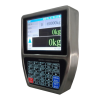
Lift the lift-arm and bucket with idle speed.
If the sensing distance between the Magnet Block and the Proximity Switch and is normal, the
buzzer will beep twice and the following arrow signs will be displayed one by one in the process
the Magnet Block passing by the Weighing Segment :
A: It’s allowed to
lift the lift-arm and bucket for weighing
.
B: The Magnet Block is passing by the Lower Proximity Switch [Lower Weighing Segment].
C: The Magnet Block is between the two Proximity Switches [Medium Weighing Segment].
D: The Magnet Block is passing by the Upper P
roximity Switch [Upper
Weighing Segment
]
.
E: It’s allowed to put the lift-arm down so that the bucket goes down to the lowest position..
After the Magnet Block passed by the Weighing Segment, display T1, T2, T3 and ACC value.
If T1 value and T3 value are near, it means that the parallelism degree in the center region of the
Magnet Block and the sensing surface of Proximity Switch is good.
Optional Adjusting Item: Adjust manually the parameter [205] ‘Run Length Ratio’.
After lifting the lift-arm and bucket with unloading and idle speed, if ACC display
value is in the range 0.0030~0.0080dm/s
2
, it’s not need to modify the set value of ‘Run
Length Ratio’; otherwise, try to modify it for ACC display value of the next lifting in
the range of empirical value 0.0050~0.0060dm/s
2
.
Increasing the set value of ‘Run Length Ratio’ will make the ACC display value
Repeat the above steps for three times, if ACC Value is stable, the adjustment process will be
Press key【Pause】to enter Pause state with red sign ‘■’ displaying.
Abnormal Arrow
Signs Display
Check if the actual operation process is correct.
Adjust
the sensing distance between the
Magnet Block and the Proximity Switch to
3~5mm.
Big Difference
between T1 and T3
Adjust the parallelism degree in the center
region of the
Magnet Block
and the sensing
surface of Proximity Switch.
Do ‘Wheel loader’s Idle Speed Adjustment’
again.