LED
Color
LED
Condition
Indication
Yellow Solid Indicates that the band is Inactive. After a period of time, if there’s no activity the band will go into sleep
mode. Light is o while band is active. This is part of normal operation.
Yellow Flashing Indicates that the Automatic Gain Control (AGC) is self-adjusting. This is part of normal operation.
Red Flashing Indicates that the booster is receiving too much signal which could cause the aected band to automati-
cally turn o. When this happens:
1. For kits using an OMNI outside antenna, relocate the outside antenna to a location where the signal is
weaker.
2. For kits using a YAGI outside antenna, turn the antenna in short increments away from the signal source.
3. Increase the separation between antennas (additional vertical separation works best).
4. Add an inline attenuator to the cable coming into the outside port of the booster.
5. As a last resort, turn down the dB gain on the dial until the light goes OFF or ashes yellow.
Yellow/
Red
Alter-
nately
Flashing
Oscillation is detected.
First, try increasing the separation between the inside and outside antennas. If your booster kit uses
two directional antennas (example: outside Yagi antenna and inside panel antenna), ensure that they are
facing away from one another.
If oscillation continues, lower the dB gain in small increments until the light turns o or ashes yellow.
Red Solid Band is o.
If a red light has been ashing for an extended time, the band will automatically shut o and display a solid
red light.
This can also happen when the booster attenuation has been turned all the way down.
WARNING: Do not attenuate the uplink and downlink dB settings below 35dB. This could cause the aected frequency band
to turn o.
Before installation, please note the following important factors:
1. A minimum of 25 ft. of separation is needed between the outside and inside antennas.
2. The booster should be positioned close to an electrical outlet.
3. Ensure sucient cable length between planned outside antenna location and booster.
Step 1. Find the Area Outside with the Strongest Signal
Before installing the outside antenna, nd the area with the strongest cellular signal from your service provider by following the
directions below:
Measure the strength of the outside cellular signal in various locations.
• Apple iPhones: Dial *3001#12345#* and press Call. In the top-left corner, a dB number appears instead of bars.
• Android devices: download apps such as “Network Signal Info” in the Google Play store to measure signal strength. Search check
real signal strength to nd other cell signal measurement apps.
• Internet: go to www.speedtest.net to test 3G and 4G data rates.
This signal booster requires a minimum cellular signal reading of -100dB at the location of the outside antenna. Signal between -70dB
and -90dB is recommended for best performance. Please note: Signal stronger than -50dB may cause the aected frequency bands to turn o.
Step 2. Install the Outside Antenna
Once you have located the area of strongest signal, mount the antenna to a pole or pipe (not included) at the highest possible
elevation. The directional Yagi antenna works best when facing the direction of your carrier’s cellular tower. To nd the location of your
carrier’s closest cell tower go to www.cellreception.com.
To install the outside antenna, assemble the u-bolt, bracket, nuts and washers as shown in the illustration. Keep the connections
loose enough to allow the antenna to rotate until the optimum direction is found.
Note: The outside antenna may be installed on a variety of pipe angles. Ensure that the
mounting area has at least a 12-inch radius clear of obstructions and other radiating
elements and orient the antenna vertically with the drip hole at the bottom.
Once the outside antenna is secured to a pipe or pole, connect one end of the provided 50
ft. coax cable to the antenna and tighten the connection.
Step 3. Install the Signal Booster and Inside Antenna
Choose a location for mounting the directional panel antenna on vertical surface. The
antenna should be at the approximate height of your cell phone when in use and facing
a central area where signal is needed. Please note: Be sure to provide enough separation
from outside antenna - at least 25 ft. Also, the outside and inside antennas should face away
from one another.
Using the plate, mark position of desired screw placement and screw mounting plate into
place with the slide panel protruding towards you (see panel antenna illustration below).
Slide antenna securely onto mounting plate.
To install the booster, select a location that is near the inside panel antenna and a working
AC outlet*. Use the supplied screws or appropriate screws for surface of mounting location
and drill through screw tab holes on booster (see Booster Components Diagram illustration)
and mount the booster to a wall.
Connect the inside antenna and booster by connecting one end of the provided 20 ft. of coax cable to the inside antenna and the
other end of the cable to the booster port marked “INSIDE” and hand-tighten the connection.
Next, connect the outside antenna and booster by connecting the remaining end of the 50 ft. cable leading from the outside antenna
to the port of the booster marked “OUTSIDE”.
Connect the AC power cord to the booster and plug into a 110V AC power outlet. Once the booster has been completely assem-
bled, turn the booster’s power switch on.
Note: If the Power LED does not turn ON or the Alert LEDs continue to ash, see the Troubleshooting section. This booster is rated for 5-15V input voltage.
DO NOT use the booster with a higher voltage power supply. This can damage the booster, cause personal injury and void your warranty.
Step 4. Congure Gain Settings
The SureCall gain dials should always be at maximum level unless the control light in a specic band is ashing red or ashing
red-yellow. In either of these cases, the rst action should be to increase the antenna isolation between the inside and outside
antenna as much as possible and restart the booster. If the situation continues, you can lower the gain with an attenuator or, as the
last resort, reduce the booster gain by 5dB at a time until the control light in the frequency band ashes yellow.
If you Want to Improve Coverage
1. Find a location that receives a stronger signal and relocate the outside antenna to that location.
2. Optimize the Yagi antenna angle.
3. Increase the distance between the outside and inside antenna.
4. Set each dial on the booster to maximum gain.
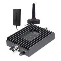
LED Indicators
Coax Cable (50 ft.)
Power Supply
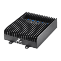
Signal Booster
Inside Antenna
Outside Antenna
Coax Cable (20 ft.)
Install Illustration
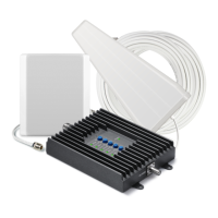
Quick Install Guide
SureCall Fusion4Home
Yagi/Panel Kit
Outside Antenna Assembly
Nut
Washer
U-bolt
Bracket
Download the complete manual at www.SureCall.com
SC-PolyH-70-YP-Kit
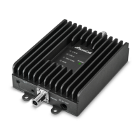
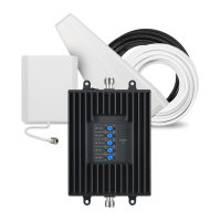
Booster
Power
Supply
Coax Cable
(50 ft. RG6 &
20 ft. SC-240)
Outside Antenna - Direc-
tional Yagi
Inside Antenna -
Directional Panel
Contents
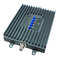
Power Jack
Power Switch
Connector to Inside Antenna
Booster Components Diagram
See the user manual, available at SureCall.com, for:
• Detailed setup instructions • Troubleshooting tips
• Product specications • Warranty information
Three-Year Product Warranty
To activate your three-year manufacturer’s warranty, register your SureCall product at www.SureCall.com
FCC, IC and Safety Information
This is a CONSUMER device.
BEFORE USE, you MUST REGISTER THIS DEVICE with your wireless provider and have your provider’s consent. Most wireless providers consent to the use of
signal boosters. Some providers may not consent to the use of this device on their network. If you are unsure, contact your provider.
You MUST operate this device with approved antennas and cables as specied by the manufacturer. Antennas MUST be installed at least 20 cm (8 inches)
from any person. You MUST cease operating this device immediately if requested by the FCC or a licensed wireless service provider.
This device may be operated ONLY in a xed location for in-building use.
WARNING: E911 location information may not be provided or may be inaccurate for calls served by using this device.
Important: Before installing your booster you need to register it with your carrier. You can do so online at the following urls:
Verizon: http://www.verizonwireless.com/wcms/consumer/register-signal-booster.html
AT&T: https://securec45.securewebsession.com/attsignalbooster.com/
T-Mobile: https://support.t-mobile.com/docs/DOC-9827
Sprint: https://www.sprint.com/legal/fcc_boosters.html
U.S. Cellular: http://www.uscellular.com/uscellular/support/fcc-booster-registration.jsp
FCC 27.50(d)(4) Statement: Fixed, mobile and portable (hand-held) stations operating in the 1720-1755 MHz band are limited 1 Watt EIRP. Fixed stations
operating in this band are limited to a maximum antenna height of 10 meters above ground. Mobile and portable stations operating in this band must employ a
means for limiting power to the minimum necessary for successful communications.
Note: This equipment has been tested and found to comply with the limits for a Class B digital device, pursuant to part 15 of the FCC Rules. These limits
are designed to provide reasonable protection against harmful interference in a residential installation. This equipment generates, uses and can radiate radio
frequency energy and, if not installed and used in accordance with the instructions, may cause harmful interference to radio communications. However, there is
no guarantee that interference will not occur in a particular installation. If this equipment does cause harmful interference to radio or television reception, which
can be determined by turning the equipment o and on, the user is encouraged to try to correct the interference by one or more of the following measures:
• Reorient or relocate the receiving antenna.
• Increase the separation between the equipment and receiver.
• Connect the equipment into an outlet on a circuit dierent from that to which the receiver is connected.
• Consult the dealer or an experienced radio/TV technician for help.
Industry Canada: This Class B digital apparatus meets all requirements of the Canadian Interference Causing Equipment Regulations. Operation is
subject to the following two conditions: (1) this device may not cause harmful interference, and (2) this device must accept any interference received,
including interference that may cause undesired operation
The Manufacturer’s rated output power of this equipment is for single carrier operation. For situations when multiple carrier signals are present, the rating
would have to be reduced by 3.5 dB, especially where the output signal is re-radiated and can cause interference to adjacent band users. This power
reduction is to be by means of input power or gain reduction and not by an attenuator at the output of the device.
Troubleshooting
Problem Resolution
Signal booster has no power Connect the power supply to an alternate power source.
Verify that the power source is not controlled by a switch that has removed power from the
outlet.
If the POWER LED on the signal booster is OFF, return the power supply to SureCall. Contact
tech support to receive an RMA at: 1-888-365-6283 or support@surecall.com
After completing installation, indoor
signal coverage has not improved
(1) Verify that all cable connections are tightly tted. (2) Try further separating the booster and
antenna. (3) Verify that there is usable signal where the outside antenna is placed.
Remember: Bars are not always a reliable measure of signal. The best way to conrm
signal coverage is the ability to place and hold a call.
Fusion4Home Specications US Canada
Uplink Frequency Range (MHz): 698-716 / 776 – 787 / 824-849 / 1850-1915 / 1710-1755 (G Block Included)
Downlink Frequency Range (MHz): 728-746 / 746 – 757 / 869-894 / 1930-1995 / 2110-2155 (G Block Included)
Maximum Gain: 72 dB
Supported Standards: CDMA, WCDMA, GSM, EDGE, HSPA+, EVDO, LTE and all cellular standards
Input Impedance: 75Ω donor port / 50Ω server port
Noise Figure: 8 dB
AC Input: Input AC110V, 60 Hz; Output DC 5-15V
Maximum Output Power: 1 Watt EIRP 3 Watt EIRP
Cable: RG6 / SC-240
RF Connectors: F Female / N Female
Power Consumption: <15W
Operation Temperature: -4º to +158º F
FCC ID / IC: RSNFUSION4H 7784A-FUSION4H
48346 Milmont Dr, Fremont, CA 94538 USA | +1-888.365.6283 | support@surecall.com | www.surecall.com© 2017. All Rights Reserved