Fl SYSTEM
DIAGNOSIS
4-35
INSPECTION
Step 1
1)
Remove the seat.
(W7-4)
2)
Turn the ignition switch OFF.
3)
Check the TO sensor coupler for loose or poor contacts.
If OK, then measure the TO sensor resistance.
"C23" TO SENSOR CIRCUIT MALFUNCTION
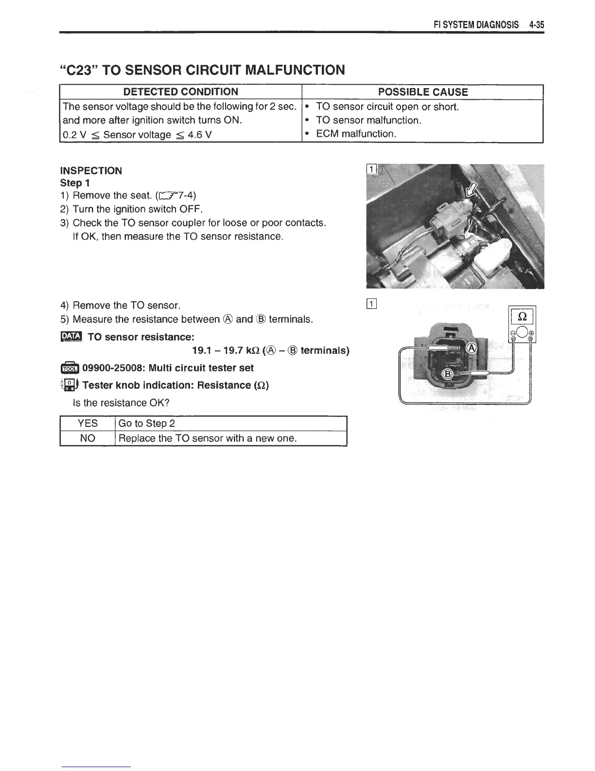
4)
Remove the TO sensor.
5)
Measure the resistance between
@
and
@
terminals.
DETECTED CONDITION
The sensor voltage should be the following for
2
sec.
and more after ignition switch turns ON.
0.2
V
5
Sensor voltage
5
4.6
V
TO sensor resistance:
19.1
-
19.7 kQ
(@
-
@
terminals)
POSSIBLE CAUSE
TO sensor circuit open or short.
TO sensor malfunction.
ECM malfunction.
09900-25008: Multi circuit tester set
fim
Tester knob indication: Resistance (Q)
Is the resistance OK?
YES
NO
Go to Step
2
Replace the TO sensor with a new one.
 Loading...