Section II: Installation - Accessories
2.5.INS.ACC.50H99
INSTALLATION INSTRUCTIONS – CAB GUARD ASSEMBLY
1. Review all directions and
diagrams provided before starting
cab guard installation.
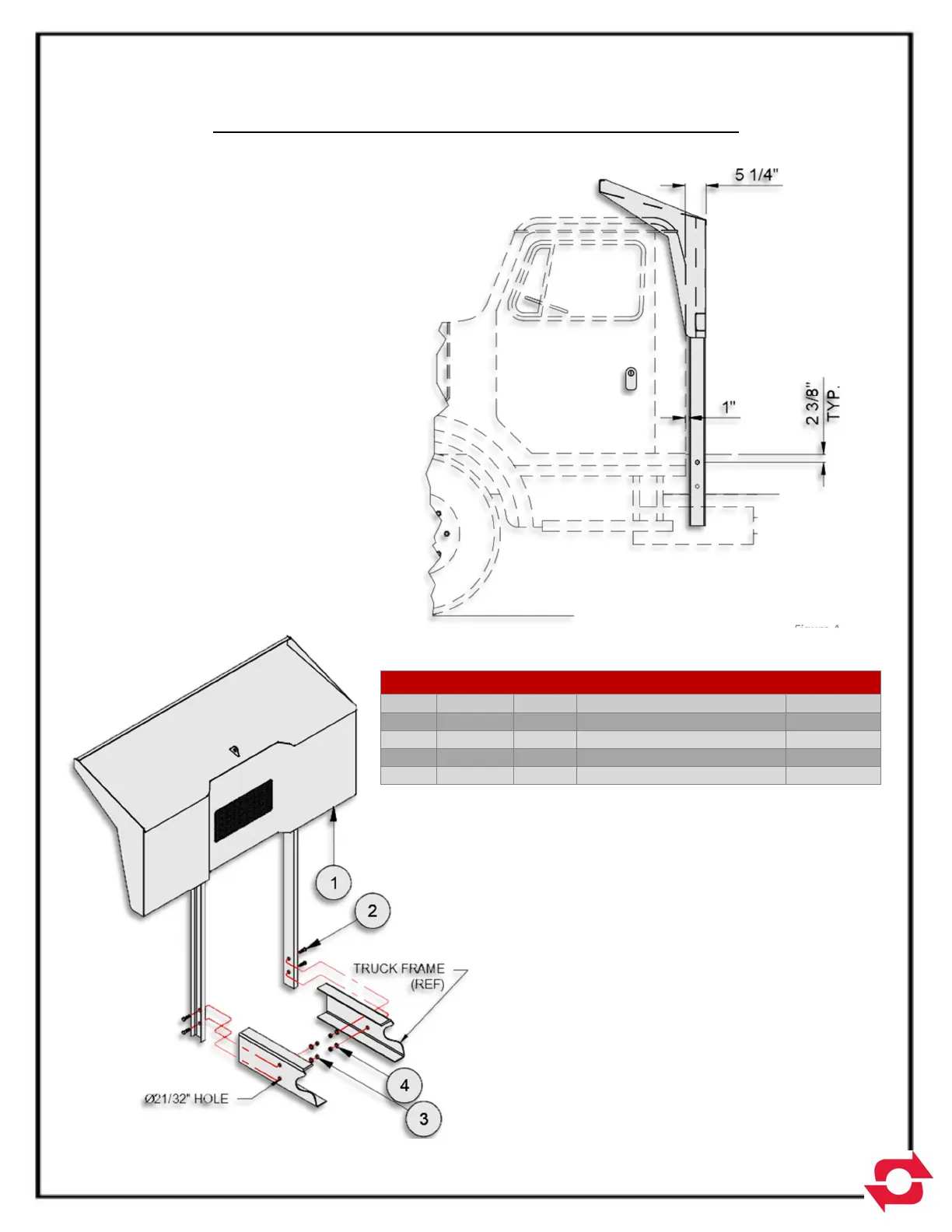
2. Position cab guard weldment (Pt.
No. 50H95) on frame with
sufficient clearance between cab
and cab guard.
3. Determine location for mounting
holes. Mounting holes should not
be located within 2 3/8” of the
truck frame edge (see Fig. A). Drill
Ø21/32” mount holes through cab
guard channels.
4. Mark mounting holes through the
cab guard weldment onto truck
frame. Remove cab guard
weldment and drill Ø2132” holes in
truck frame.
5. Attach cab guard weldment to
truck frame using fasteners
provided (see Fig. B).
MATERIAL LIST FOR 50H99
ITEM PART # QTY DESCRIPTION WT-lb/ea.
1 50H95 1 Cab Guard Wdmt 295.36
2 00P69 4 5/8-11 X 2 HHCS 0.33
3 00P55 4 5/8-11 Locking Hex Nut 0.18
4 00785 4 Ø5/8” Washer Ht 0.08
Figure A
Figure B