Section II: Installation
CONTROLS INSTALLATION – MANUAL
1. Attach the valve mount bracket (Pt. No. 10H51) to the main frame as indicated on Pg.
5-11 with the fasteners provided (see Pg. 5-7).
2. Mount the hydraulic control valve assembly (Pt. No. 21P32) to the valve mount bracket
as shown on Pg. 5-11 with the fasteners provided.
3. Install the hydraulic adapters, connect the hydraulic tubing & hoses (Pt. Nos. 12P53,
12P59, & 13P12) to the control valve assembly as indicated on Pg. 5-9. The tubing
should be supported by the clamp assemblies that are provided in the Loose Parts Box
(see Pg. 5-7).
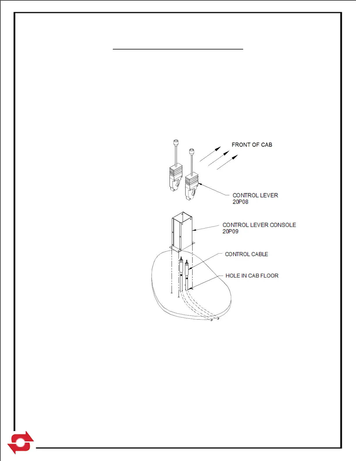
4. Determine the best location
in the cab for the control
levers (Pt. No. 20P08). The
location should be such that
the controls can be easily
reached while operating the
truck. A control lever
console (Pt. No. 20P09) is
provided to facilitate the
mounting of the control
levers (see Pg. 5-11).
5. Assemble and install the
control lever console (see
Fig. F below). Typically the
console is fastened to the
floor of the cab and the
control cables are routed
through additional holes
drilled in the floor. Your
particular installation may
require that additional
brackets be fabricated or
other modifications made.
6. Attach the control cables to the control levers and route the cable through the holes in
the cab. Install the control levers in the console. Levers should be installed such that
when the levers are pushed forward the control cable is extended. See Pg. 5-11
(Manual Control Assembly) for control lever orientation.
7. Route the cables to the control valve location and attach them to the control valve with
the bonnet connection kits provided (Pt. No. 20P10). See the following instruction sheet
for installation procedures. The control cables supplied are 84 inches long. Your
particular mounting may require different length control cables, which can be purchased