DEVYL ARTIC
20
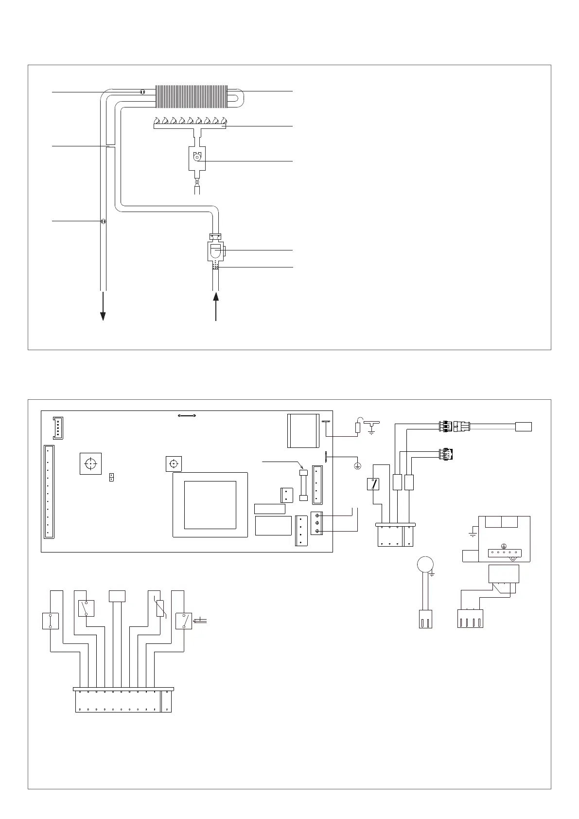
2.3 Water circuit
1 Limit thermostat
2 By-pass (only DEVYL ARTIC 11-13)
3 NTC sensor
4 Exchanger
5 Burner
6 Gas valve
7 Flow switch
8 Filter
Hot water outlet Cold water inlet
1
2
4
5
6
7
3
8
2.4 Multi-wire electrical diagram
CN7
CN5
JP1
P1
P2
JP4
RL1
RL3
CN1
CN4
CN2
CN3
T1
T2
F
N
L
230 V
E.A./R.
1
1
F= Fuse 2 AF
1
11
1
4
FA1
FA2
V
CN3
marrone
blu
1
2
marrone
CN4
1
2 3
4
blu
rosa
3
2
1
5
4
1 2 43
OPE OPE
VALVOLA GAS
MOD
T.L.
grigio
bianco
bianco
nero
nero
rosso
rosso
viola
viola
MOD
P.F.
S.S.
grigio
F.L.
CN7
111
bianco
AMP
RFS
bianco
blu
marrone
1
2
3
4
nero
nero
G1
G2
blu
marrone
marrone
blu
CN2
T.AG.
1
2
3
AMP
3
2
1
2
3
1
AMP
NOTE: L-N POLARISATION IS RECOMMENDED
IWH01NX Control diagram
T1 Transformer
T2 Ignition transformer
P1 DHW temperature selection potentiometer
P2 OFF-ON selector
JP1 NG-LPG selection jumper
RL1 Fan relay
RL3 Ignition control relay
F Fuse 2A F
CN1-CN7 Connectors
E.A./R. Ignition/Detection electrode
T.L. Limit thermostat
P.F. Flue gas pressure switch
MOD Modulator
S.S. DHW circuit temperature probe (NTC)
FL DHW flow switch
V Fan
OPE Gas valve operator
T.A.G. Antifreeze thermostat
G1-G2 Joints
RFS Wire-wound heating element
Bianco White
Nero Black
Grigio Grey
Rosso Res
Viola Purple
Marrone Brown
Blu Blue
Rosa Pink
Valvola gas Gas valve
fig. 2
fig. 3