1-7-3 T5307EA
4-2. C-Trap Adjustment
Purpose: To get minimum leakage of the color signal
carrier.
Symptom of Misadjustment: If C-Trap Adjustment is
incorrect, stripes will appear on the screen.
Note: J233 (B-Out)--- Main CBA
1. Connect Oscilloscope to J233.
2. Input a color bar signal from RF input.
Enter the Service mode. (See page 1-4-1.)
3. Press "0" button on the remote control unit and
select C-TRAP Mode.
4. Press CH o / p buttons on the remote control unit
so that the carrier leakage B-Out (3.58MHz) value
becomes minimum on the oscilloscope.
5. Turn the power off and on again.
4-3. Y DL Time Adjustment
Purpose: To get minimum leakage of the color signal
carrier.
Symptom of Misadjustment: If Y DL Time Adjust-
ment is incorrect, stripes will appear on the screen.
1. Enter the Service mode. (See page 1-4-1.)
2. Press "0" button on the remote control unit twice to
show "D-T" on the display.
3. Select "2" by pressing CH o / p buttons on the
remote control to enter Y DL Time Adjustment
mode.
4. If needed, perform the following.
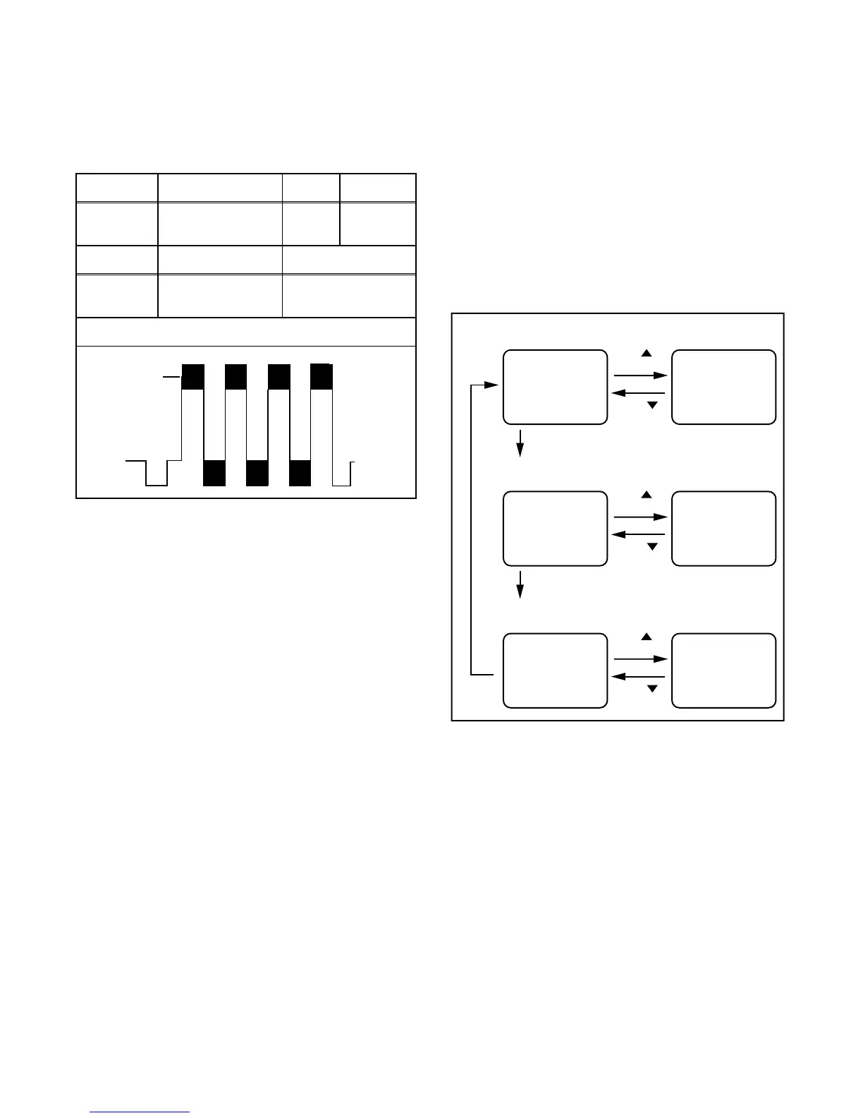
Test point Adj. Point Mode Input
J233
(B-OUT)
CH o / p
buttons
--- Color Bar
Tape M. EQ. Spec.
---
Oscilloscope
Pattern Generator
---
Figure
minimum
Fig. 2
Y DL Time Adj TV Adjustment
CH
button
D-T TV 0 D-T TV 1
button
CH
Y DL Time Adj EXT/PB Adjustment
CH
button
D-T EXT 0 D-T EXT 1
button
CH
"0" button
"0"
button
C-TRAP Adjustment (Factory mode)
CH
button
C-TRP 0 C-TRP 1
button
CH
"0" button