16. Electrical Equipment
16-24
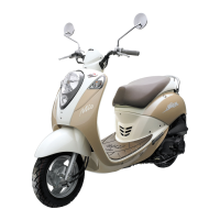
Brake light switch
The circuit of black wire and the green/yellow wire
on the brake light switch should be in continuity
when operating the brake lever.
If the switch damaged, replace it with new one.
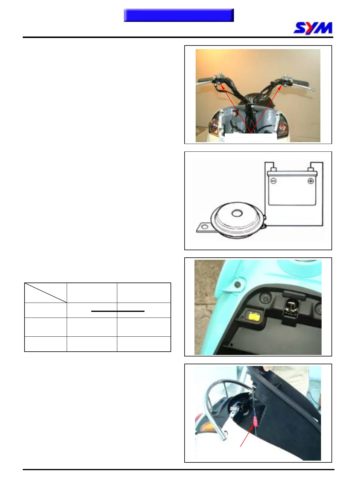
Horn
Remove the front fender.
Connect the light blue wire on the horn to the
battery positive (+) terminal, and the green wire to
the battery negative (-) terminal. Then, the horn
should sound.
Replace it if necessary.
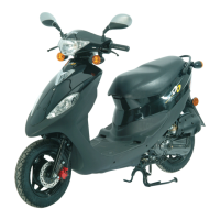
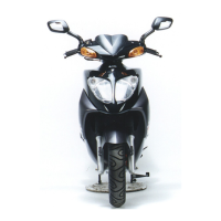
Engine Start Control Switch
Remove luggage box, and then remove engine
start control switch.
Pin
Location
L/Y L/Y
OFF
● ●
ON
Wire color Blue / Yellow Blue / Yellow
Engine start control
switch coupler
Brake light switch
To this chapter contents