ZV-3405 REV 0
IMPORTANT / FOR INSTALLER
WARNING:
As the installer of this valve, you must first carefully read and understand the material covered in this manual before
installing and adjusting this valve per instructions. Failure to do so may compromise the installation, operation and/or
serviceability of this valve.
DO NOT install positive shut-o devices on the outlet of this valve, or devices that do not allow the valve to flow at
least 1.5 GPM at 45 psi inlet pressure. Exception: If a self-closing or slow-closing valve is installed on the outlet, the
supplies of the valve must be equipped with checks to eliminate hot to cold bypass in the event the valve’s handle is
not turned o after use.
When installing this valve, failure to adjust limit stop screw properly may result in serious scalding.
COMPLIANCE
-ASME A112.18.1/CSA B125.1
-ASSE 1016
-Buy American Act Compliant
LIFETIME LIMITED WARRANTY
All warranty claims MUST be pre-approved by Symmons.
All parts and finishes of the Symmons products are
warranted to the original consumer purchaser to be free
from manufacturing defects in material and workmanship
for 5 years Non-Residential or Commercial Applications.
Symmons warrants to the original consumer purchaser/
end-user that any Symmons product will be free of
defects in material and workmanship during normal
domestic use for the life of your home.
Symmons recommends using a professional plumber
for all installation and repair. During the warranty
period, Symmons at its sole option, will provide
replacement part(s) or product (or, if no longer available,
a comparable product) to replace those which have
proven defective in materials or workmanship under
normal installation, use and service, FREE OF CHARGE
for the time period of 5 years from the date of purchase.
(BATTERIES NOT INCLUDED)
This warranty is extensive in that it covers replacement of
all defective parts and even finish, but these are the only
two things that are covered. Damage due to installation
error, product abuse, product misuse, or use of cleaners
containing abrasives, alcohols, or other organic solvents,
whether performed by a contractor, Service Company
or yourself are excluded from this warranty. Symmons
will not be responsible for labor charges and/or damage
incurred in installation or repair or replacement, nor for
any indirect, incidental or consequential damages, losses,
injury or costs of any nature relating to the bathing
products. Except provided by law, this warranty is in
lieu of and excluded all other warranties, conditions and
guarantees, whether expressed or otherwise, including
without restriction those of merchantability or of fitness
for use.
Some states do not allow the exclusion or limitation
of incidental or consequential damages, so the above
limitation of exclusion may not apply to you. This
warranty gives you specific legal rights, and you also may
have other rights which vary from state to state. This
warranty is not transferable. This warranty does not cover
damage or defects relating to misuse, abuse, negligence,
normal wear and tear, accident, acts of God, repairs or
alterations not authorized in writing by Symmons, or
improper installation, storage or handling.
The above mentioned warranty information includes each
product that falls under the following: Symmons Bathing
Products Warranty- Non-Residential or Commercial
Applications; Symmons Non-Electronic Lifetime
Faucet and Finish Limited Warranty Non-Residential or
Commercial Applications; Symmons Electronic Faucet
Limited Warranty - Non-Residential, Commercial and
Residential Applications; Symmons Bathing Products
Warranty- Residential Application Symmons Non-
Electronic Lifetime Faucet and Finish Limited Warranty
Residential Application
If you have any questions regarding technical support,
installation or concerns regarding our warranty plan,
please email us at GetHelp@symmons.com or call us at:
1-800-796-6667.
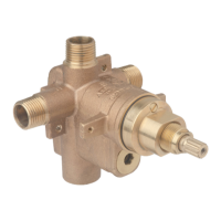
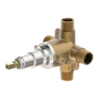
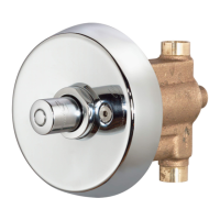
S261BODY
VOLUME CONTROL
Temptrol
®
Pressure Balancing Valve
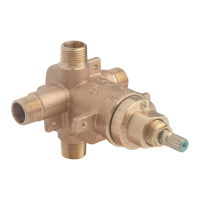
S261BODY, S261XBODY
Installation Instructions
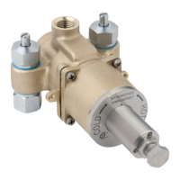
S261XBODY
EASYSERVICE™
STOPS