1-11-8
T2127SCM6
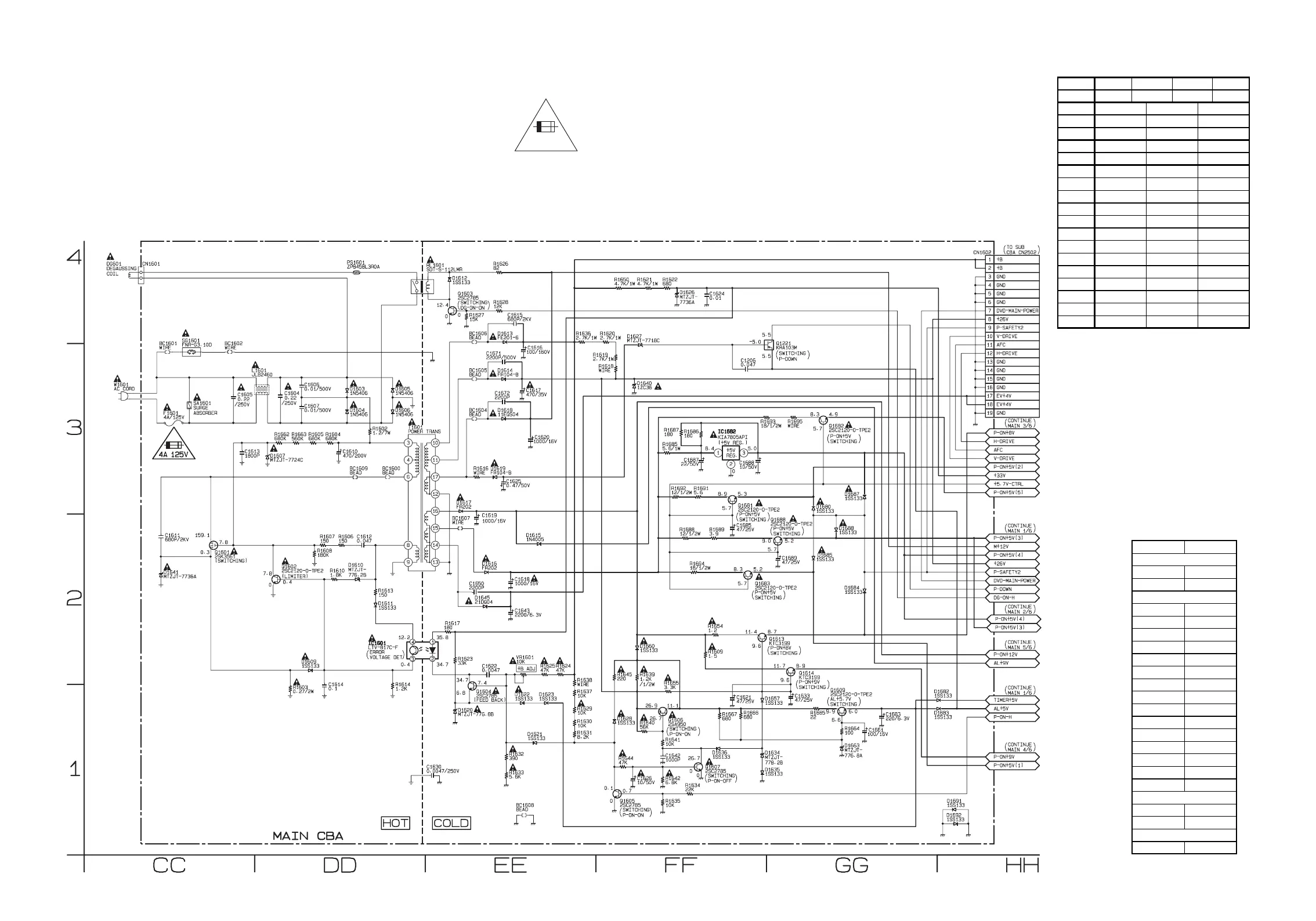
Main 6/6 Schematic Diagram < TV/VCR Section >
VOLTAGE CHART (Power off mode)
Ref. No. 1 4
IC1601 12.0 1.6
Ref. No.
IC1682
Ref. No.
Q1601
Ref. No.
Q1221
Q1602
Q1604
Q1605
Q1606
Q1607
Q1609
Q1613
Q1614
Q1681
Q1682
Q1683
Q1688
3.2
0.9
0.4 3.2
0.9
0.3
0.3 3.2 0.9
0.8 3.2
0.9
0.8 8.1 1.4
0.9 8.1 1.4
00.10.7
5.9 8.2 6.5
08.00
9.2 9.2 8.6
01.80.3
6.8 10.9 7.4
ECB
5.3 5.3 3.5
SDG
0 164.2 1.8
123
3.1 0 1.9
23
10.9 0.3
NOTE:
The voltage for parts in hot circuit is measured using
hot GND as a common terminal.
For continued protection against risk of fire,
replace only with same type 4 A, 125V fuse.
CAUTION ! :
ATTENTION : Utiliser un fusible de rechange de même type de 4A, 125V.
4A 125V
CAUTION !
Fixed voltage (or Auto voltage selectable) power supply circuit is used in this unit.
If Main Fuse (F1601) is blown , check to see that all components in the power supply
circuit are not defective before you connect the AC plug to the AC power supply.
Otherwise it may cause some components in the power supply circuit to fail.
MAIN 6/6
Ref No. Position
IC1601 DD-2
IC1682 FF-3
Q1221
GG-3
Q1601 CC-2
Q1602 DD-2
Q1603 EE-4
Q1604 EE-1
Q1605 FF-1
Q1606 FF-1
Q1607 FF-1
Q1609 GG-1
Q1613 GG-2
Q1614 GG-2
Q1681 FF-3
Q1682 GG-3
Q1683 FF-2
Q1688 GG-2
CN1601
CC-4
CN1602 HH-4
VR1601 EE-2
CONNECTORS
ICS
VARIABLE RESISTOR
TRANSISTORS