EasyManuals Logo

SYNAPTICON SOMANET Node 400 Hardware Manual

Default Icon
67 pages
To Next Page IconTo Next Page
To Previous Page IconTo Previous Page
Page #51 background imageLoading...
Page #51 background image
6 BY- Bypass- Connect to BY+ (Pin 1) to bypass STO/SBC
1.6.3.1.2 Wiring examples for the STO/SBC inputs
The wiring differs depending on the safety device used:
Manual switch covers any emergency device that can be connected directly to the safety input of the
servo drive.
If safety PLCs are used it is important to distinguish between plus-plus and plus-minus logic
PLCs using plus-plus logic must be connected to both inputs for redundancy
PLCs using plus-minus logic are only connected to the input 1 which must be bridged to input 2.
The redundant channel in this case is the pulsed safety ground signal.
Important
Please note that Safety GND is an isolated signal from drive GND.
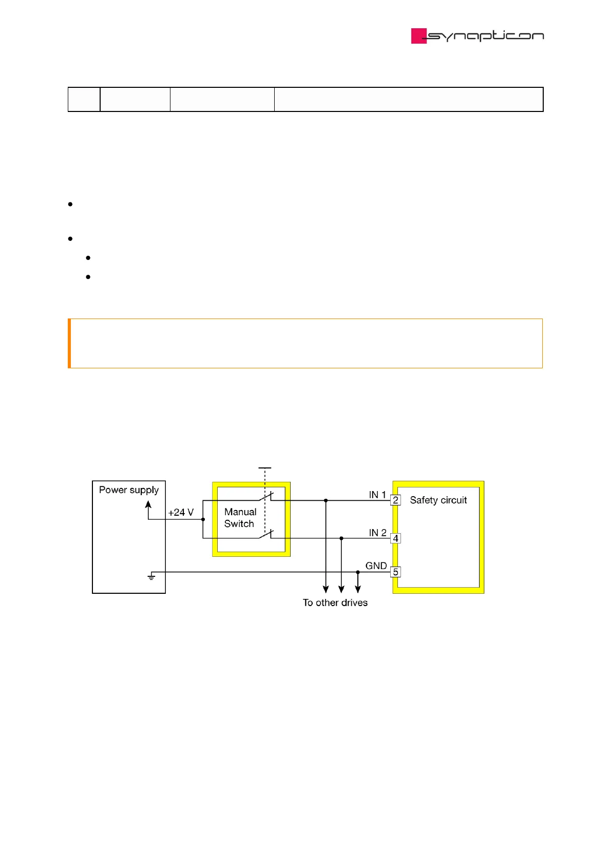
1.6.3.1.2.1 Manual switch
Allows safety functions up to SIL 3, PL e, cat.3.
Hardware Manuals / SOMANET Node / SOMANET Node rev. E.1
© 2021 Synapticon GmbH | Daimlerstraße 26 | D-71101 Schönaich Documentation v 4.10.2 | Built 2021-07-06 51/67

Table of Contents

Other manuals for SYNAPTICON SOMANET Node 400

Questions and Answers:

Question and Answer IconNeed help?

Do you have a question about the SYNAPTICON SOMANET Node 400 and is the answer not in the manual?

SYNAPTICON SOMANET Node 400 Specifications

General IconGeneral
BrandSYNAPTICON
ModelSOMANET Node 400
CategoryServo Drives
LanguageEnglish

Related product manuals