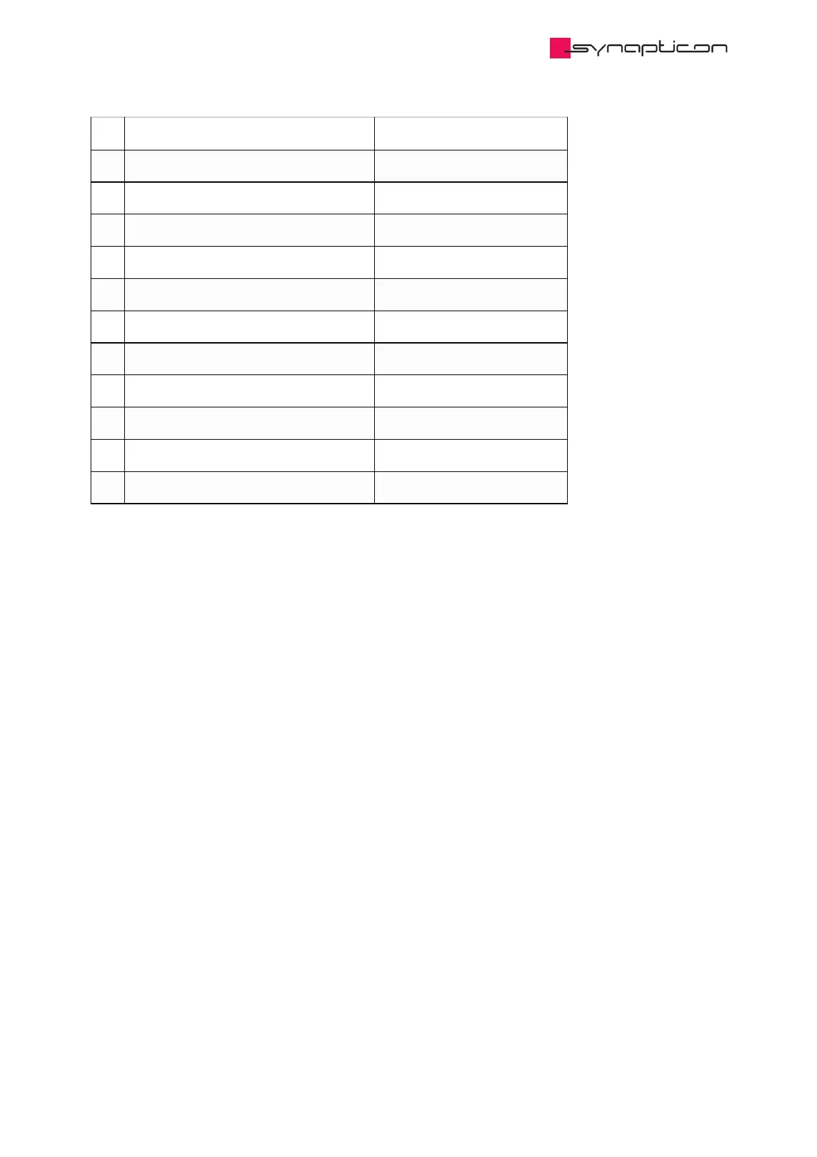
1 –
2 Analog Input 1 - Connect to Ground **
3 Analog Input 1 + Single-ended 0-10 V
4 Ground
5 Analog Input 2 - Connect to Ground **
6 Analog Input 2 + Single-ended 0-10 V
7 5 V ***
8 10 V ****
9 Analog Input 3 - Differential ±5 V
10 Analog Input 3 + Differential ±5 V
11 Analog Input 4 - Differential ±5 V
12 Analog Input 4 + Differential ±5 V
* All Analog Inputs can be configured as single-ended 0-5 V, 0-10 V, 0-20 V or differential ±5 V, ±10 V
independently.
Upon request only, please contact sales@synapticon.com
** Must be connected to Ground when the Analog Input is set to Single-Ended Mode.
It is recommended to use a separate ground cable for each single-ended analog signal/cable and twist
or tie them together.
*** This is a 5 V supply that can provide up to 100 mA for external use.
The supply is protected against short to ground and keeps the current below 400mA in a continuous
short.
**** This is a 10 V supply that can provide up to 25 mA for external use.
The supply is protected against short to ground and keeps the current below 100mA in a continuous
short.
Error Before Calibration: 1.5%
 Loading...

