EasyManuals Logo
Home>SYNAPTICON>Servo Drives>SOMANET Node Series

SYNAPTICON SOMANET Node Series Documentation

Default Icon
27 pages
To Next Page IconTo Next Page
To Previous Page IconTo Previous Page
Page #20 background imageLoading...
Page #20 background image
1.3.4 Grounding and connecting a brake
Please make sure you ground the board properly.
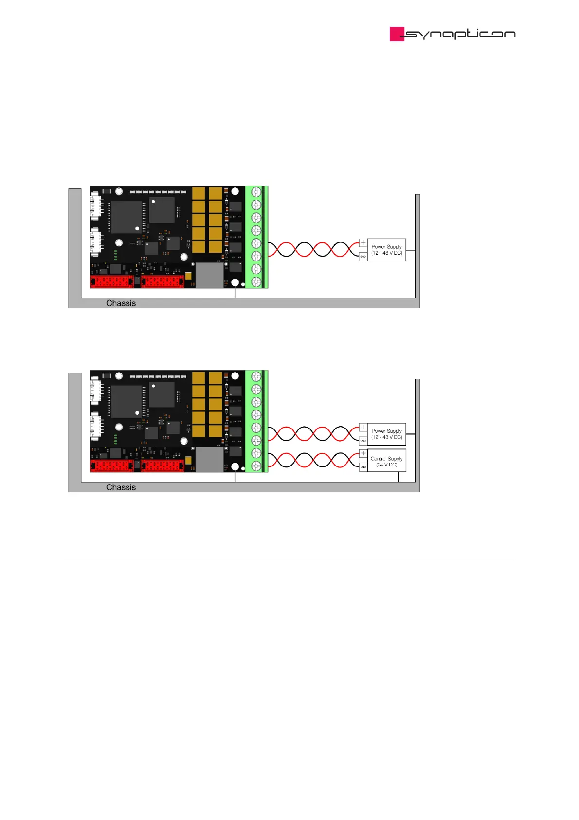
Your configuration will look like this:
In case you have additional Logic Supply, please wire your module like this:
1.3.4.1 Connecting a Brake
If your system has an attached brake, please connect the brake cables to Phase D and Ground. These
two threads should be twisted together or at least be paired to have a minimum area between them.
By default, Logic Supply is deactivated, it is therefore recommended to use Logic Ground (pin 7 of the
Main Supply Connector) for the brake.
Hardware Manuals / SOMANET Node / SOMANET Node rev.
D.3/D.4
© 2020 Synapticon GmbH | Daimlerstraße 26 | D-71101 Schönaich Documentation v 4.2.0 | Build: 2020-10-02 20/27

Other manuals for SYNAPTICON SOMANET Node Series

Questions and Answers:

Question and Answer IconNeed help?

Do you have a question about the SYNAPTICON SOMANET Node Series and is the answer not in the manual?

SYNAPTICON SOMANET Node Series Specifications

General IconGeneral
BrandSYNAPTICON
ModelSOMANET Node Series
CategoryServo Drives
LanguageEnglish

Related product manuals