getting started
6
SSYNRAD OEM v30 Operator’s Manual Version 2
Caution
possible
equipment
damage
SYNRAD does not recommend mounting lasers in a vertical “head-
down” or “tail-down” orientation. If you must mount your laser in
this manner, please contact the factory for limitations as a vertical
orientation increases the risk of damage to the laser’s output optic.
Mounting
The OEM v30 base plate is designed so the laser is easily mounted using three 1/4–20 UNC or M6 × 1 ISO
fasteners. Three ball bearing “feet” pressed into the base plate eliminate any possible distortion of the laser
tube caused by variations in the atness of the mounting surface. Refer to OEM v30 package outline draw-
ings in the Technical Reference chapter for mounting locations and dimensions.
Important Note: To prevent possible distortion of the tube, you must fasten the v30 base plate di-
rectly to your mounting surface.
To fasten the OEM v30 laser to your mounting surface, perform the following steps:
1
Refer to the appropriate v30 outline & mounting drawing and drill three holes into your mounting
surface that correspond to either the UNC or metric hole pattern.
2
Place the v30 laser on the mounting surface so that the threaded holes in the base plate line up with
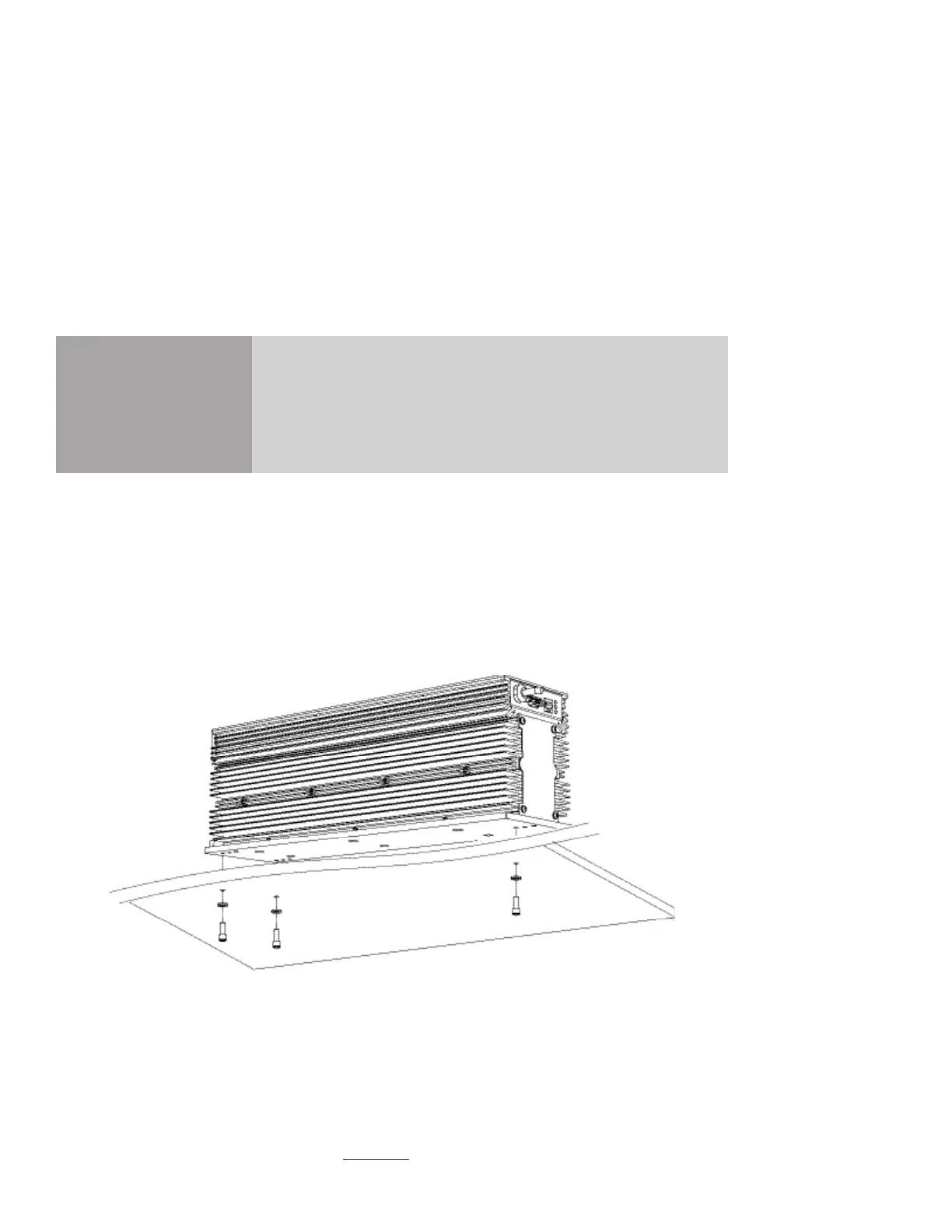
the holes in your mounting surface as shown in Figure 1-2.
Figure 1-2 OEM v30 mounting locations (1/4–20 fastener locations shown)
Note: Mounting bolts must not extend further than 6.0 mm (0.24") into the v30 base plate.
3
Insert three M6 × 1 ISO or 1/4–20 UNC capscrews through the mounting surface into the threaded
holes of the v30 base plate. Turn the screws by hand until the threads engage.
4
Evenly tighten all three capscrews to a maximum torque of 6.1 N m (54 in lb).