technical reference
45
SYNRAD OEM v30 Operator’s Manual Version 2
Interface connections
DB-9 input circuitry
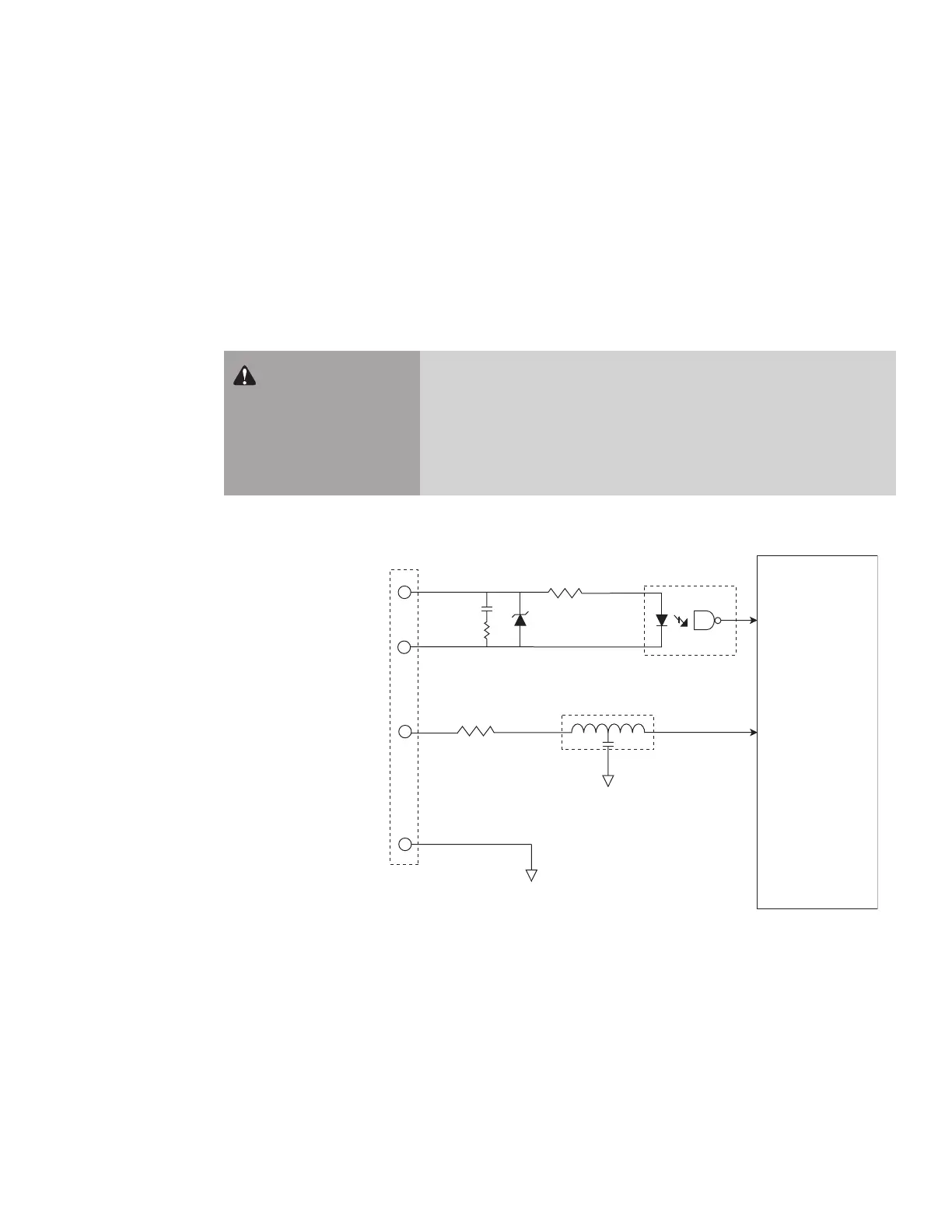
The Interface A (DB-9) connector has two user inputs—a PWM input and an enable input. As described
in Table 3-3, PWM Positive and PWM Negative are optoisolated to fully isolate PWM Command signals
from other inputs and outputs. The Laser Enable input is ESD protected, but is not optoisolated, so this
input signal must be conditioned by the user.
Figure below illustrates the input circuit’s equivalent internal schematic while the prior table on the fol-
lowing page provides DB-9 input circuit specications.
Figure 4-5 DB-9 input equivalent schematic
Warning
serious
personal
injury
Always use shielded cable when connecting your PWM Command
signal source to PWM Positive/PWM Negative inputs. In electrical-
ly-noisy environments, long lengths of unshielded wire act like an
antenna and may generate enough voltage to trigger uncommanded
lasing.
DB-9 (INTERFACE A) CONNECTOR – INPUT PINS
PWM POSITIVE (+) (1)
TIVE (–) (6)
LASER ENABLE (9)
GND (8)
100 Ohm
FIRESTAR v30
INPUT CIRCUITRY
430 Ohm
EMI Filter