technical reference
47
SYNRAD OEM v30 Operator’s Manual Version 2
Interface connections
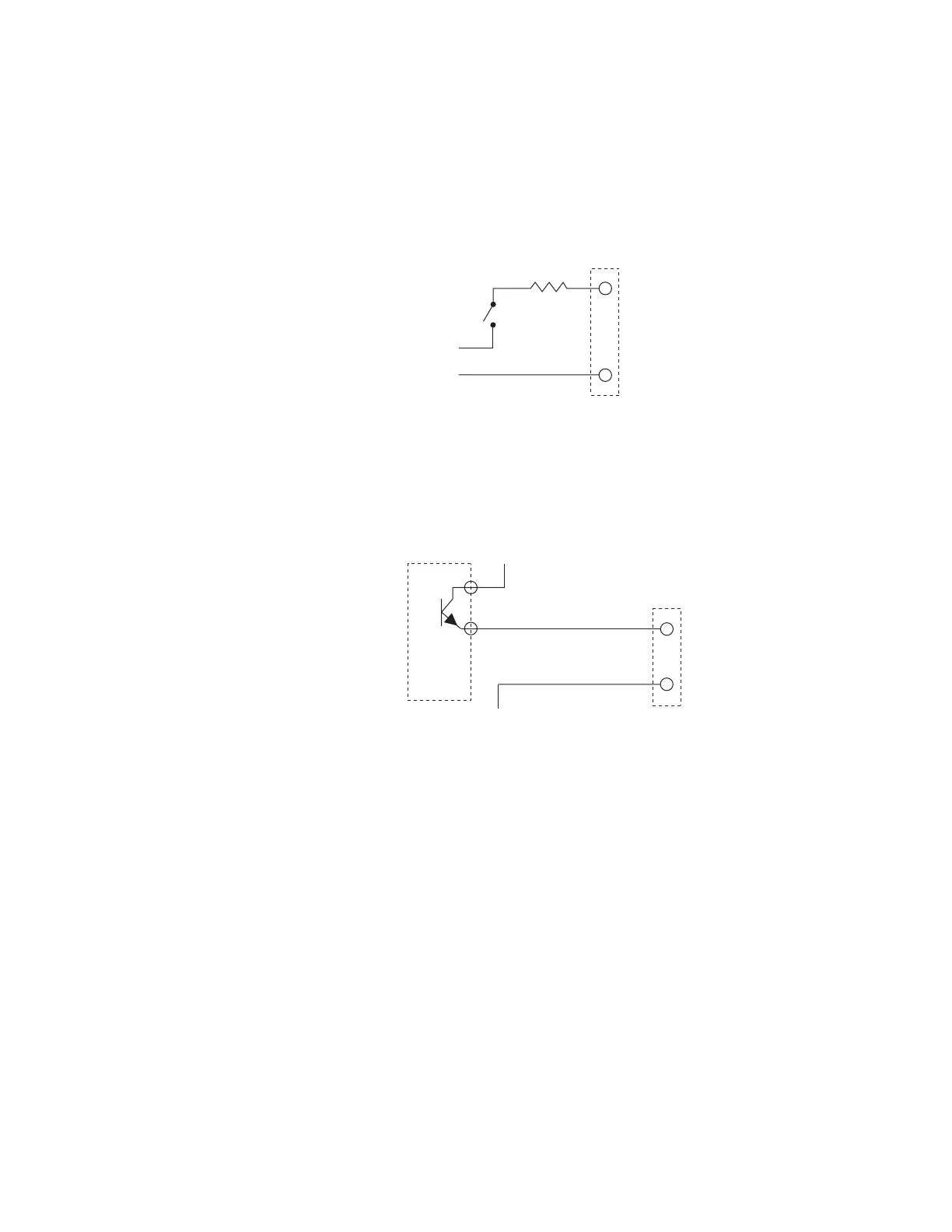
Figure below shows another variation for applying a Laser Enable signal. In this case, the
customer is also supplying the voltage necessary to drive the v30’s enable circuit.
Laser enabled when
switch or contact closed
DB-9 (INTERFACE A) CONNECTOR PINS
(9)
(8) GND
100 Ohm
+5 VDC
5 VDC RETURN
Figure 4-7 Customer powered Laser Enable circuit
Figure below shows an isolated PLC output module switching the Laser Enable signal from a
+5 V source.
Figure 4-8 PLC switched Laser Enable circuit
DB-9 output circuitry
The Interface A (DB-9) connector has four user outputs that communicate laser status to the user’s con-
trol system. As described in Table 4-3, the four outputs, Laser Ready, Lase Indicator, Overtemp Fault, and
DC Voltage Fault are ESD protected, but are not optoisolated. The Laser Ready output goes high (+5V)
when lasing is possible, otherwise the output is low (0V) when the laser is not ready. Lase Indicator goes
high when the PWM signal is sucient to induce laser output and is low when no beam is being emit-
ted. Overtemp Fault goes high when laser temperature rises above its upper thermal limit; otherwise
the output is low. DC Voltage Fault goes high when an under/over voltage condition is sensed; other-
wise the output is low when the DC supply voltage is within limits.
Note: OEM v30 outputs are voltage sources. Each output can source only 20 mA typical, 40 mA maxi-
mum, to a ground referenced load (the ground reference, GND, is Pin 8). The control board will
be damaged if this current limit is exceeded.
The Interface A (DB-9) connector also includes a +5 VDC output voltage source, DC Out. This output
can provide a maximum current of 250 mA and is useful for driving the Laser Enable input as described in
the DB-9 input circuitry subsection.
DB-9 (INTERFACE A) CONNECTOR PINS
(9)
(8) GND
PLC
ISOLATED
DC
OUTPUT
MODULE
output energized