technical reference
53
SYNRAD OEM v30 Operator’s Manual Version 2
Interface connections
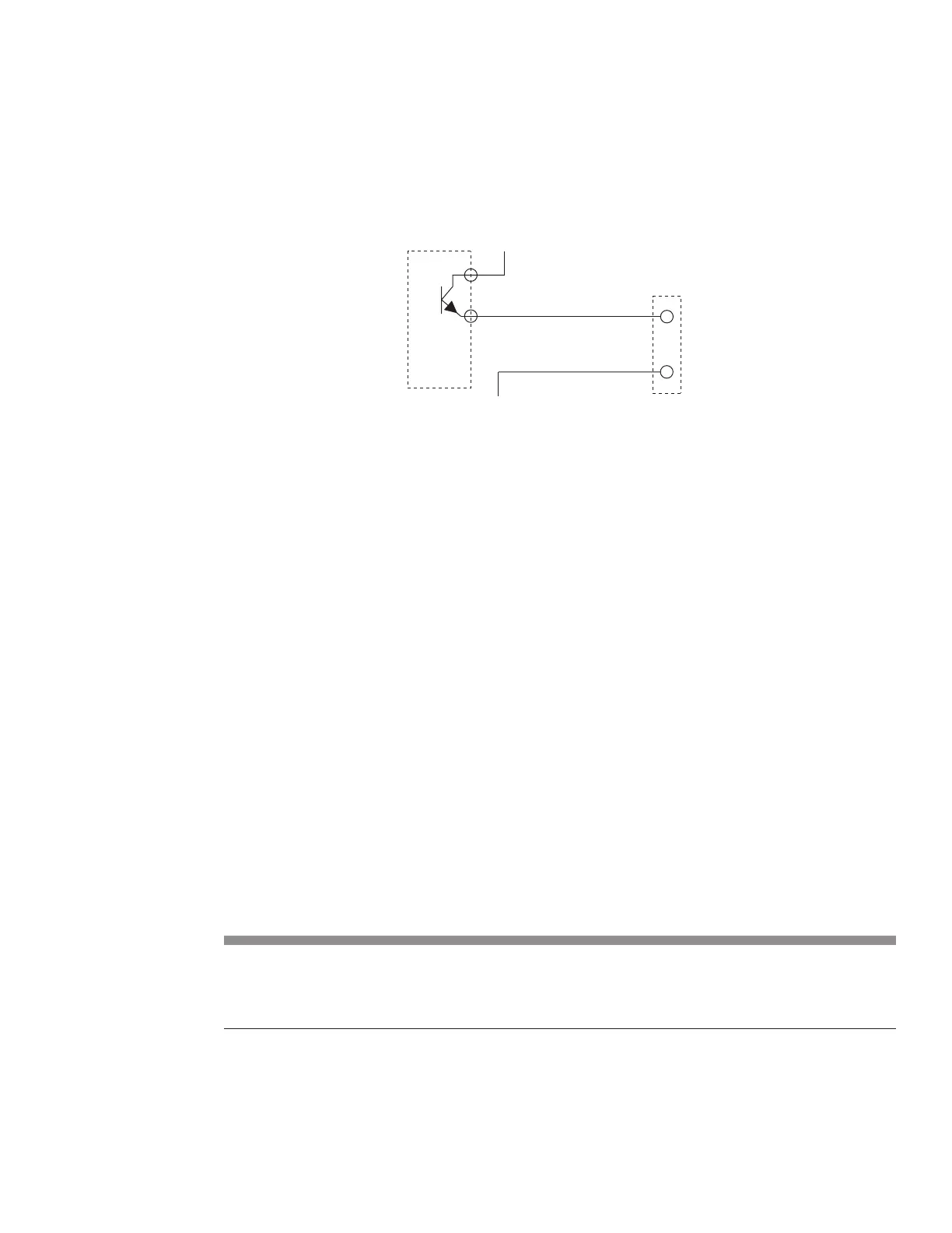
Figure below shows an isolated PLC output module switching the Laser Enable signal from a
+5 V source.
Figure 4-14 PLC switched Laser Enable circuit
RJ45 output circuitry
The Interface B (RJ45) connector has three user outputs that communicate laser status to the user’s control
system. As described in Table 3-6, the three outputs, Laser OK, Temperature OK, and Voltage OK are
ESD protected, but are not optoisolated. The Laser OK output is high (+5V) when lasing is possible, oth-
erwise the output goes low (0V) when a fault is detected. Temperature OK is high when laser temperature
is within limits; otherwise the output goes low if laser temperature rises above thermal limits. Voltage OK
is high when the DC supply voltage is within limits; otherwise the output goes low if an under/over voltage
condition is sensed.
Note: OEM v30 outputs are voltage sources. Each output can source only 20 mA typical, 40 mA maxi-
mum, to a ground referenced load (the ground reference, GND, is Pin 8). The control board will
be damaged if this current limit is exceeded.
The Interface B (RJ45) connector also includes a +15 VDC output voltage source, DC Out, that provides a
maximum current of 250 mA.
Table below provides RJ45 output circuit specications while the following gure illustrates the output
circuit’s equivalent internal schematic.
Table 4-8 RJ45 output circuit specications
Output Signals Output Device Type and Specications
Laser OK 5V logic output buer
Temperature OK On state Vmin +4.5 VDC @ 50 mA
Voltage OK On state (typical) +5.0 VDC @ 0.5 mA
O state Vmax +0.8 VDC
RJ45 (INTERFACE B) CONNECTOR PINS
(7)
(8) GND
PLC
ISOLATED
DC
OUTPUT
MODULE
output energized