technical reference
54
SYNRAD OEM v30 Operator’s Manual Version 2
Interface connections
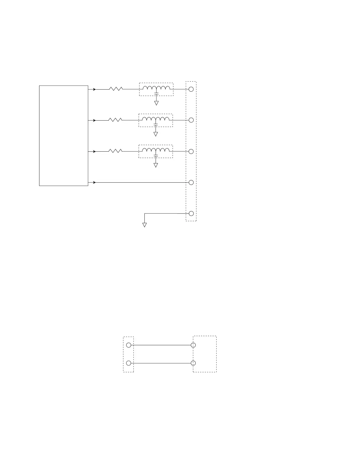
Figure 4-15 RJ45 output equivalent schematic
Sample output circuit
You can monitor OEM v30 laser status remotely by connecting one or more outputs to an
isolated 5 VDC solid state relay or PLC input module. Figure below illustrates the connections
required to monitor the RJ45’s Laser OK status, or any other RJ45 output, using an isolated 5
VDC input module.
FIRESTAR v30
OUTPUT CIRCUITRY
RJ45 (INTERFACE B) CONNECTOR – OUTPUT PINS
(3) LASER OK
(4) TEMPERA
(5) VOLTAGE OK
(2) DC OUT
(8) GND
15 VDC, 250 mA
100 Ohm
EMI Filter
100 Ohm
EMI Filter
100 Ohm
EMI Filter
Figure 4-16 Laser OK output to PLC input
RJ45 (INTERFACE B) CONNECTOR PINS
LASER OK
GND
ISOLATED
INPUT
MODULE
IN1
COM1