technical reference
66
SYNRAD OEM v40 Operator’s Manual Version 4
User I/O connections
Auxiliary DC power
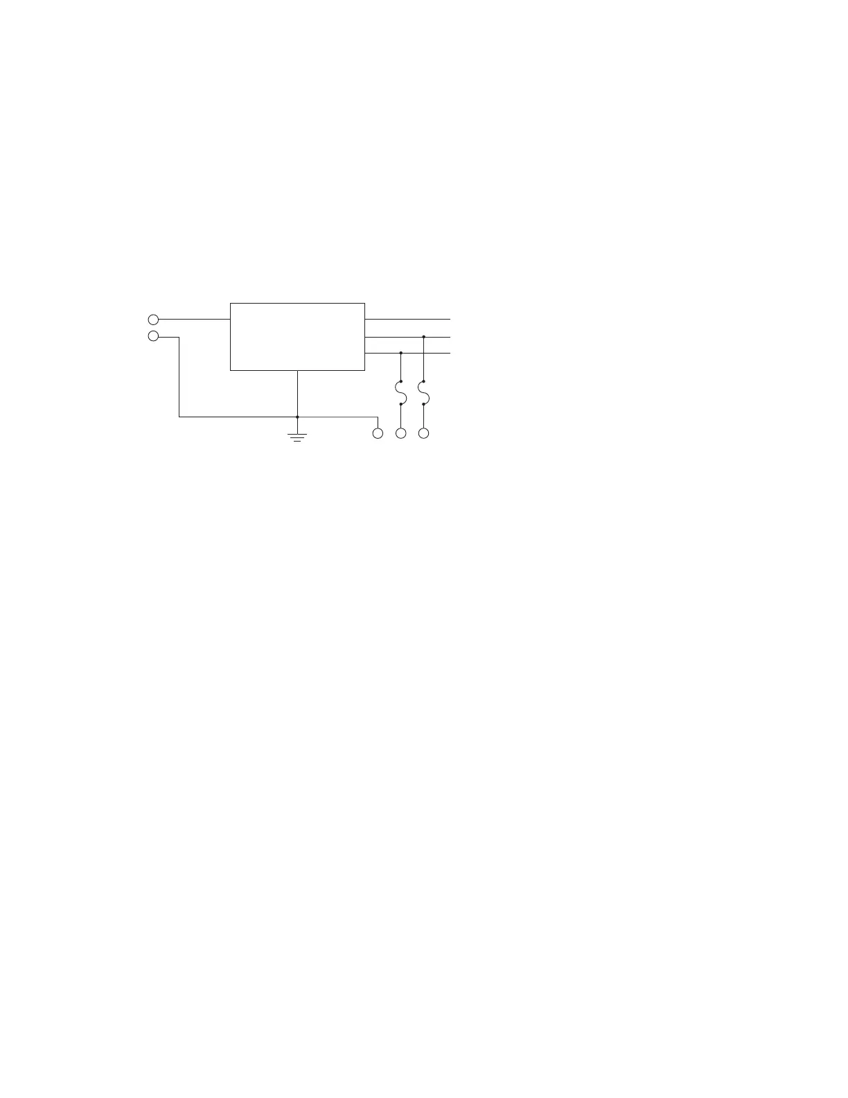
Firestar’s User I/O connector provides auxiliary DC power for driving external inputs or outputs connect-
ed to the User I/O port. Pin 4, +5 VDC Auxiliary Power, and Pin 5, +24 VDC Auxiliary Power, are protected
by self-resetting fuses rated at 0.5 A. Pin 12, Auxiliary DC Power Ground, is connected to chassis ground
while all other User I/O pins are oating with respect to chassis ground. Figure below illustrates Firestar’s
internal DC supply wiring.
Figure 4-6 Auxiliary power supply wiring
Pin 4 + 5 VDC Auxiliary Power
This connection provides +5 VDC for driving external inputs or outputs. The + 5 VDC Auxiliary
Power output can source up to 0.5 A and is protected by a 0.5 A self-resetting fuse. The return
(ground) path must be through Pin 12, Auxiliary DC Power Ground.
Pin 5 + 24 VDC Auxiliary Power
This connection provides +24 VDC for driving external inputs or outputs. The + 24 VDC
Auxiliary Power output can source up to 0.5 A and is protected by a 0.5 A self-resetting fuse. The
return (ground) path must be through Pin 12, Auxiliary DC Power Ground.
Pin 12 Auxiliary DC Power Ground
This connection provides a ground (earth) connection for +5 and +24 VDC auxiliary power out-
puts. This pin is the only User I/O pin that is connected to the laser’s chassis ground. Do not use
this pin for grounding if I/O circuits are powered from an external customer-supplied DC power
source.
+30 VDC TO RF GENERATOR
VOLTAGE REGULATORS
AND
30 V SWITCH
CHASSIS GROUND (EARTH)
0.5 A FUSE
SELF-RESETTING
0.5 A FUSE
SELF-RESETTING
+24 VDC (INT. FANS/EXT. I/O POWER
+5 VDC (INTERFACE LOGIC)
(12) (4)
(5)
+30 VDC (+)