operation
44
SYNRAD OEM v40 Operator’s Manual Version 4
Keyswitch controls and indicators
v40 rear panel
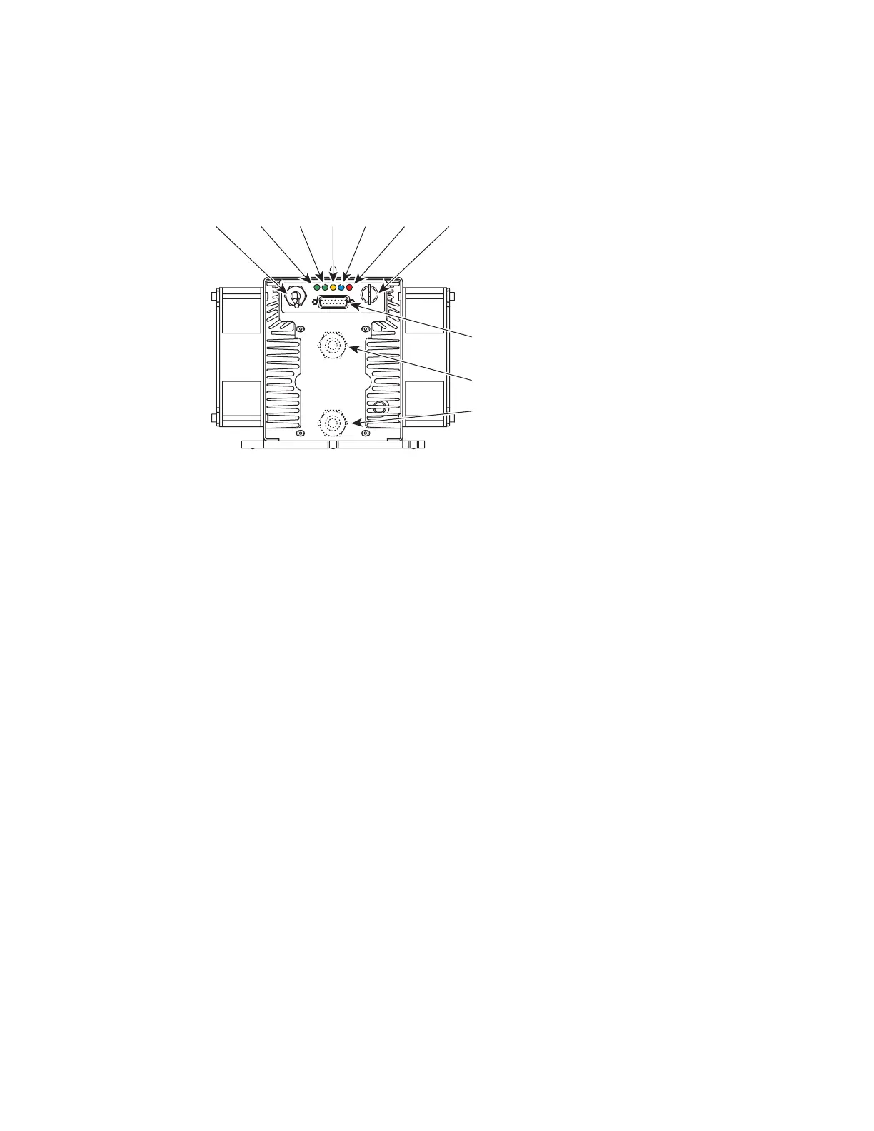
Figure 3-2 Keyswitch v40 rear panel controls and indicators
1
DC Power Cables – receives 30 VDC from the DC power supply. The red (positive) cable contains a
replaceable 25A in-line fuse.
2
INT (Remote Interlock) Indicator – illuminates green to indicate that a remote interlock circuit is
closed and that lasing may be enabled. The INT indicator is red and lasing is disabled if the interlock
input is open.
3
TMP (Temperature) Indicator – illuminates green to indicate that laser temperature is within limits
and that lasing may be enabled. The TMP indicator is red and lasing is disabled if the laser’s tem-
perature rises above safe operating limits.
4
RDY (Ready) Indicator – illuminates yellow when the laser is enabled, indicating that, after a ve-
second delay, lasing will begin when a PWM Command signal is applied.
5
SHT (Shutter) Indicator – illuminates blue to indicate that the shutter is Open and that lasing may
be enabled. The SHT indicator is o and lasing is disabled if the shutter is Closed. When the shutter
is switched Open, there is a ve-second delay until PWM inputs are recognized.
6
LASE Indicator – illuminates red to indicate that Firestar is actively lasing. The LASE indicator is
o when tickle pulses are being generated and illuminates red when PWM Command signal pulses
are long enough to produce laser output.
7
Keyswitch – enables/disables operation of the laser. The laser is enabled when the Keyswitch is turned
to the ON position. Turn the Keyswitch OFF to disable lasing.
8
USER I/O Connector – provides a connection point for auxiliary output power as well as input and
output signals. Refer to the Technical Reference chapter for pinouts and signal descriptions.
9
WATER IN Port (water-cooled only) – labeled IN, this connection provides the cooling water inlet
to Firestar’s water-cooling system.
10
WATER OUT Port (water-cooled only) – labeled OUT, this connection provides the cooling water
outlet from Firestar’s water-cooling system.
ON
OFF
USER I/O
INT
TMPRDY SHT
LASE
(Fan-Cooled v40 Shown)
1
2
4
5
7
9
8