technical reference
72
SYNRAD OEM v40 Operator’s Manual Version 4
User I/O connections
Sample I/O circuits
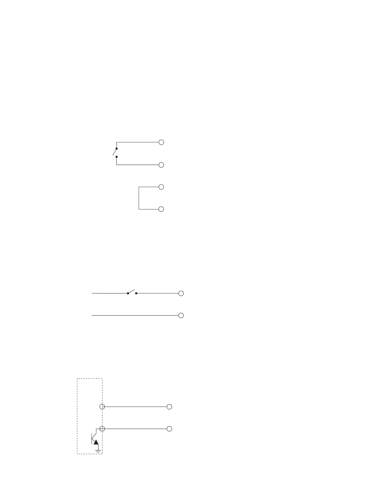
Sample inputs
Figure below illustrates one method of supplying a Remote Interlock signal using a customer-supplied
limit switch. Firestar’s +24 VDC Auxiliary Power output powers the circuit. Note that Pin 4, +5 VDC Auxil-
iary Power, could have been used instead, depending on circuit voltage requirements.
Figure 4-10 Customer-supplied interlock
Figure below shows another variation for supplying a Remote Interlock signal to the laser. In this case,
the customer is using a limit switch and supplying a negative voltage to drive Firestar’s input circuit.
(12) AUX. DC POWER
Close switch to
le interlock
(5) +24 VDC AUXILIARY
POWER
(3) REMO
(11) INPUT COMMON
enable interlock
(3) REMO
TE INTERLOCK
(11) INPUT COMMON
–12
VDC
0 VDC
Figure 4-11 Customer-supplied interlock, negative voltage
A Programmable Logic Controller (PLC) can also drive Firestar inputs. Figure below shows a typical
method for connecting to a PLC output module when only one Firestar input is used.
USER I/O PINS
(3) REMO
(11) INPUT COMMON
PLC
DC
OUTPUT
MODULE
+V
(+5–24V)
Figure 4-12 PLC driven interlock signal