operation
45
SYNRAD OEM v40 Operator’s Manual Version 4
OEM controls and indicators
The OEM controls and indicators section includes subsections:
■ OEM v40 front panel
■ OEM v40 rear panel
■ OEM v40 air side panel
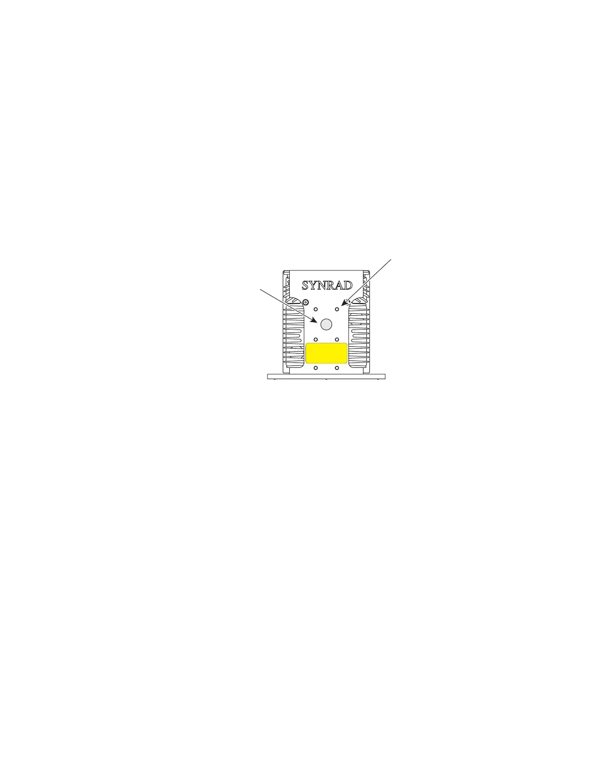
OEM v40 front panel
Figure 3-3 OEM v40 front panel controls and indicators
1
Laser Aperture – provides an opening in Firestar’s front panel from which the beam exits.
2
Optical Accessories Mounting – provides six threaded holes (8–32 UNC) for mounting optional
beam delivery components available from SYNRAD. Because excessive weight may damage the
laser, consult SYNRAD before mounting components not specically designed as Firestar options.
Refer to Firestar package outline drawings in the Technical Reference chapter for mounting hole
dimensions.
3
DP Power Connector (not shown) – standard except on OEM air-cooled (SAB) models. Provides
a convenient +5 VDC, 50 mA receptacle to power a visible red diode pointer (available from
SYNRAD as an optional accessory).
Note: When mounting optical components to v40 lasers, the 8–32 UNC fasteners must extend no
further than 0.19" (4.8 mm) into the laser’s faceplate.
(Air-Cooled v40 OEM Shown)
1
2
AVOID EXPOSURE
Invisible laser radiation
is emitted from
this aperture.