technical reference
75
SYNRAD OEM v40 Operator’s Manual Version 4
DB-9 connections
(SAB models only)
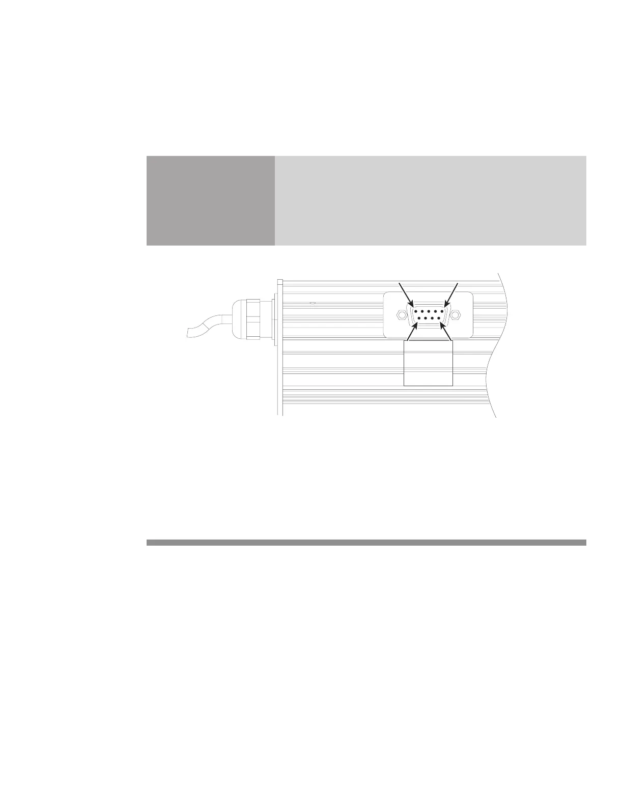
The side-mounted DB-9 connector on SAB model lasers provides a Shutter Switch input as well as auxil-
iary +5 and +24 VDC power. Figure below illustrates DB-9 pinouts.
Caution
possible
equipment
damage
+5 VDC (Pin 9) and +24 VDC (Pin 4 and Pin 5) voltage outputs
are not fused or electrically protected. Do not short these pins; the
control board will be damaged.
Pin 6Pin 9
Figure 4-17 DB-9 connector pinouts
Table below describes the function of each pin on the DB-9 connector.
Table 4-6 Side-mounted DB-9 pin descriptions
Pin Function Description
1 No Connection
2 No Connection
3 DC Power Ground
This connection provides a return (ground) connection for Pin 4 and Pin 5 (+24 VDC Fan
Power), and Pin 9 (+5 VDC Auxiliary Power). This pin is the only DB-9 pin connected to
chassis ground. Do not use this pin if DC power is supplied from an external customer-sup-
plied DC power source.
4 + 24 VDC Fan Power
This output provides +24 VDC for driving a customer-supplied cooling fan. The +24 VDC
Fan Power output (Pin 4) can source up to 0.75 A max. This pin is not protected or fused;
the control board will be damaged if this pin is inadvertently shorted. The return (ground)
path must be through Pin 3, DC Power Ground.