technical reference
74
SYNRAD OEM v40 Operator’s Manual Version 4
User I/O connections
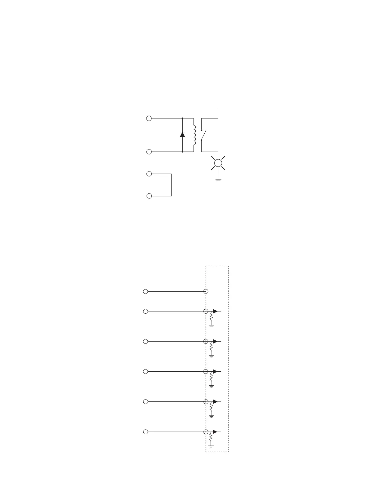
Figure below illustrates a method for controlling a higher voltage, higher current load by using a 24 V
control relay. Ensure that the relay coil’s pull-in current does not exceed 50 mA. A diode or surge sup-
pressor must be installed across the relay coil to prevent voltage spikes from damaging Firestar outputs.
+24 VDC AUXILIARY
WER
LASER ACTIVE
AUX.DC POWER
OUND
L
Figure 4-15 Firestar output driving relay
Figure below illustrates how Firestar’s outputs can drive the DC Input Module of a Programmable Logic
Controller (PLC). By supplying voltage (+VDC) to Pin 13, Output Common, each Firestar output is inde-
pendently switched to activate individual PLC inputs.
USER I/O PINS
PLC
DC
INPUT
MODULE
OUTPUT COMMON
LASER ACTIVE
OVER TEMPERATURE
LASER READY
SHUTTER OPEN
INTERLOCK OPEN
V+
(+5–24V)
Figure 4-16 Firestar output driving PLC input module