technical reference
73
SYNRAD OEM v40 Operator’s Manual Version 4
User I/O connections
When multiple PLC outputs are required, connect Firestar inputs to the PLC as shown in Figure below. By
supplying voltage (+VDC) to Pin 11, Input Common, and pulling individual inputs to ground, each input
can be independently activated by the PLC’s output module.
PLC
DC
OUTPUT
MODULE
+V
(+5–24V)
USER I/O PINS
(11) INPUT COMMON
(2) REMOTE RESET/STAR
(3) REMOTE INTERLOCK
(10) SHUTTER OPEN REQUEST
Figure 4-13 Multiple PLC driven inputs
Sample outputs
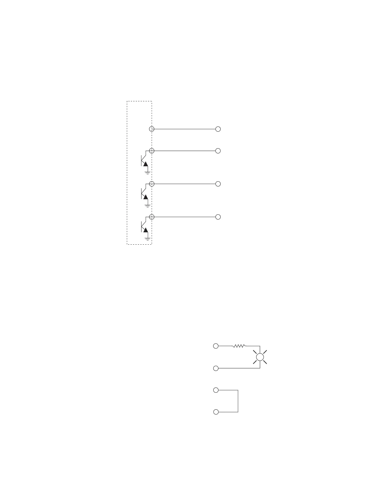
Firestar’s optoisolated bi-directional switched outputs can drive small loads (50 mA max), PLC inputs, or
relays that can control higher current loads. Figure below illustrates one method of controlling a remote
warning lamp using power supplied by Firestar’s +24 VDC Auxiliary Power output. Remember to size
current-limiting resistor, R1, so that the current draw does not exceed 50 mA.
+24 VDC AUXILIARY
WER
LASER ACTIVE
AUX. DC POWER
OUND
L
R1
Figure 4-14 Firestar output driving warning lamp