technical reference
65
SYNRAD OEM v40 Operator’s Manual Version 4
User I/O connections
Input/output signals
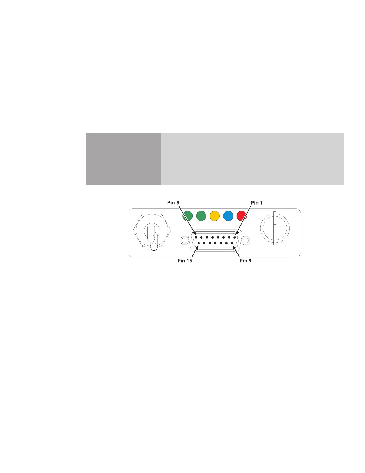
Firestar’s input/output signals are divided into three categories: auxiliary DC power, input signals, and
output signals. Signals in each category are fully described in the section below. Figure below illustrates
the pin arrangement of the User I/O (15-pin female D-type subminiature) connector on Firestar’s rear
panel.
Note: See DB-9 connections later in this section for signal descriptions and pinouts of the SAB model’s
side-mounted DB-9 connector.
Caution
possible
equipment
damage
Turn o DC power before installing or removing any plug or cable
from the User I/O connector. Ensure that user connections are made
to the appropriate pins and that the appropriate signal levels are ap-
plied. Failure to do so may damage the laser.
Figure 4-5 User I/O connector pinouts
USER I/O
ON
INT
TMP RDYSHT LASE
OFF