technical reference
69
SYNRAD OEM v40 Operator’s Manual Version 4
User I/O connections
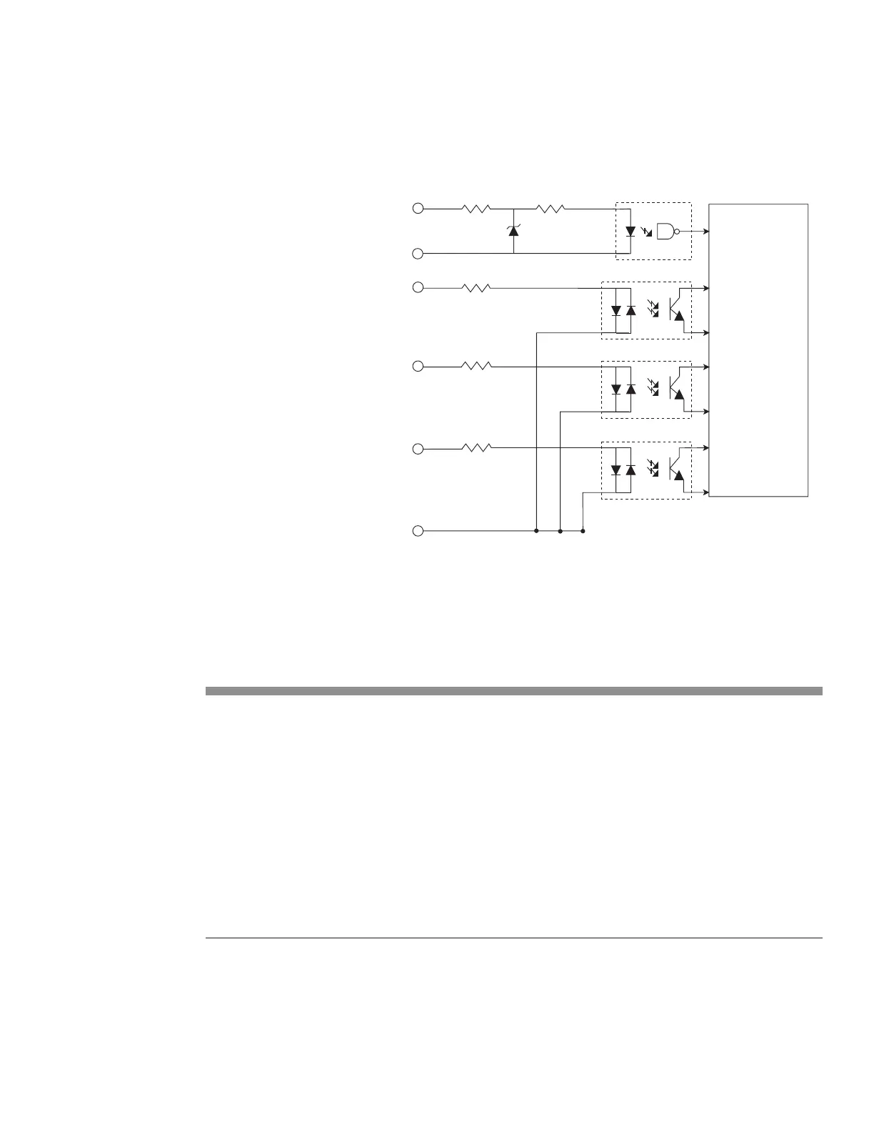
Figure 4-8 Input equivalent schematic
Table 4-4 Input circuit specications
Input Signal Name Input Device Type and Specications
PWM Input High-speed optoisolator LED (forward voltage drop (Vf) 1.5 VDC)
O state Vmax +0.8 VDC
On state Vmin +3.5 VDC @ 3 mA
On state (continuous) Vmax +6.7 VDC @ 10 mA
Frequency, max. 25 kHz
Remote Reset/Start Request Bi-directional optoisolator LED (Vf = 1.15 VDC)
Remote Interlock O state Vmax < 1.0 VDC
Shutter Open Request On state Vmin ±5.0 VDC @ 7 mA
On state (continuous) Vmax ±24.0 VDC @ 40 mA
Note: The Remote Reset/Start Request input must not be sent until Firestar’s +5 VDC power supply
has stabilized (approximately 200 ms after DC power-up).
USER I/O INPUT SIGNAL PINS
PWM INPUT (+) (9)
PWM RETURN (–) (1)
TE RESET/START REQUEST (2)
REMOTE INTERLOCK (3)
SHUTTER OPEN REQUEST (10)
600 Ohm, 2 W
600 Ohm, 2 W
600 Ohm, 2 W
FIRESTAR v40
INPUT CIRCUITRY
220 Ohm, 1/8 W
430 Ohm, 1/10 W