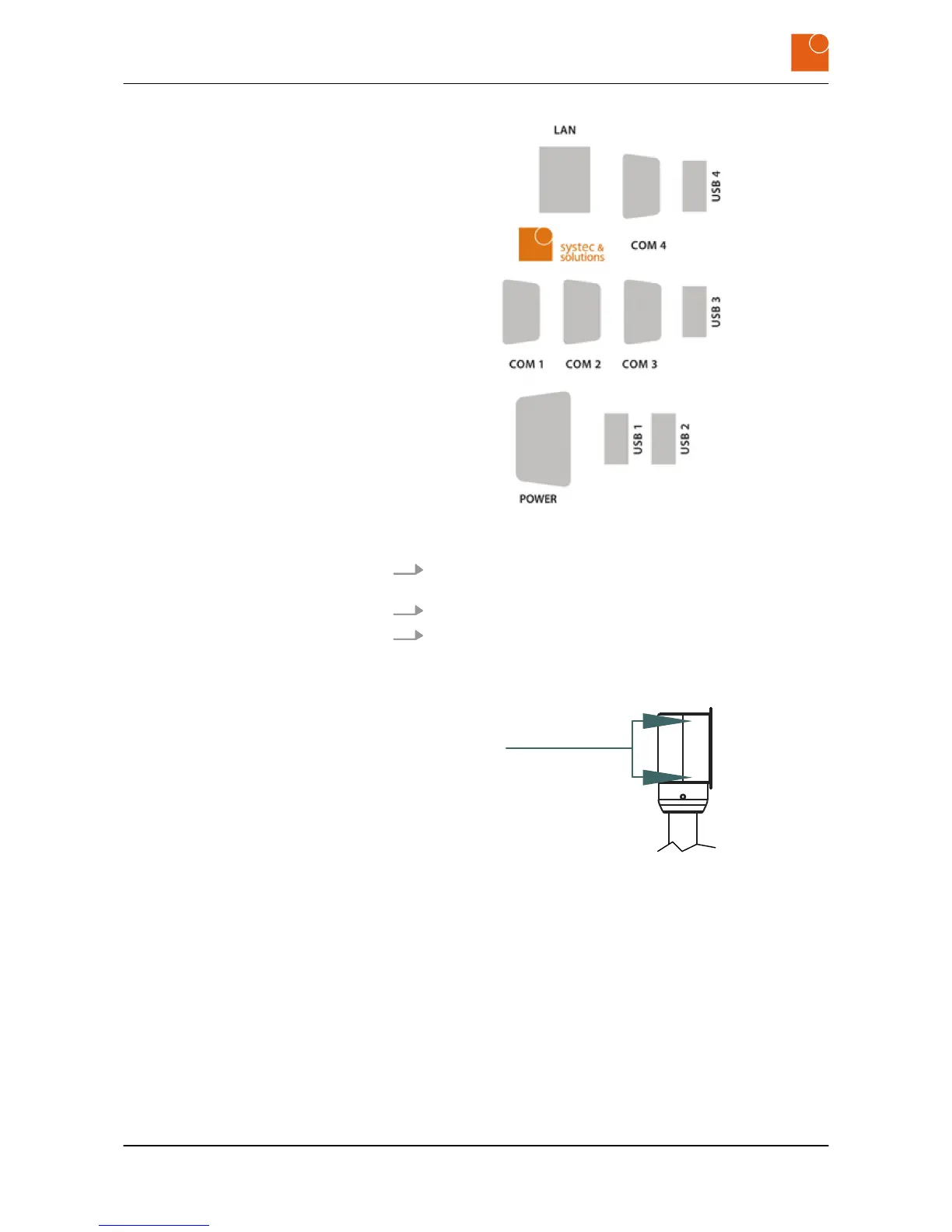
Fig. 18: Interface plate on the rear of the WAVE 224 monitor/thin client
(depending on the configuration)
4. Connect up all the cables between the interface plate and the
equipment rack adapter.
5. Tighten the screws on the mains plug.
6. Fasten the WAVE 224 monitor/thin client to the equipment rack
adapter using the four M5 x 16 screws.
You will find a view of the backplane in section
Ä
Chapter 3.4
“Dimensions” on page 15.
Fig. 19: Screw connections on the equipment rack adapter
ð
The WAVE 224 monitor/thin client is now mounted.
Starting up
Mounting the device
WAVE 224 monitor/thin client - Industrial monitor/thin client
24
 Loading...