pag.
8
Industrial PC - COPILOT 15" Mini-ITX
Order Code 2E00xxxxNovember 2020 - Rev. 1.3
Table 4.3.4
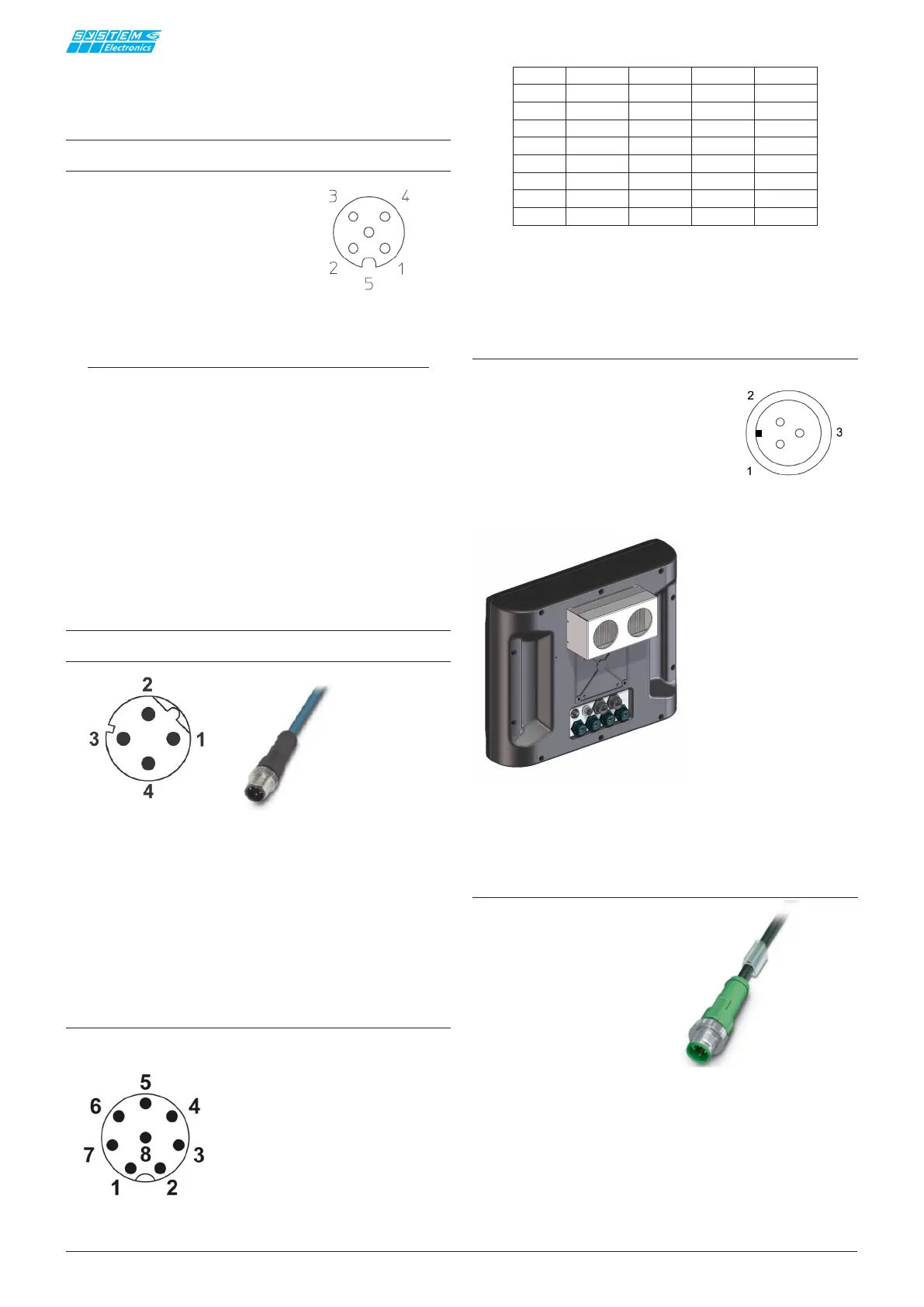
Optional Peltier cooler connection:
Removable 3-pin bayonet connector.
• 1 +24Vdc (23-25 Vdc max)
• 2 GND
• 3 PE
Figure 4.3.5 View of External Male Connector
Figure 4.3.6 Rear view of the Peltier cooler version
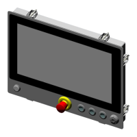
Opzione cavo di collegamento ali-
mentazione
Figure 4.3.7 Power supply cable cod. E7805105008 - length 3m)
• 1 BROWN
• 2 WHITE
• 3 BLUE
• 4 BLACK
• 5 YELLOW/GREEN
4.3 Wiring diagram for exter-
nal M12 connectors
24V power supply
M12 Female 5-pole A
• 1 +24V
• 2 +24V
• 3 GND
• 4 GND
• 5 PE
Figure 4.3.1 External female connector views
NOTE:
The connection of pins 2 and 4 is designed to mi-
nimize losses due to small cable cross section. If
necessary, the alternative connection that can be
used is as follows:
• 1 +24V
• 2 n.c.
• 3 GND
• 4 n.c
• 5 PE
Ethernet (IEC 61076-2-101 standard)
M12 Polarized Female D
Figure 4.3.2 M12 cable with male connector
• 1 TX+
• 2 RX+
• 3 TX-
• 4 RX-
COM1/COM2 [M12 Male 8 Poles].
COM1 wiring (internally selectable as RS232/RS422/
RS485)
Figure 4.3.3 External male connector view
PIN RS232
RS422 RS485
1
2
RX RX+
3TXTX- D-
4
5
GND GND GND
6
RTS
7CTS
8
___ ___ ___
BITBUS
RT-
D-
GND
TX+ D+ D+
RX-RT+