3
System Sensor™ Smoke Sensor Model 2100ARFT
Mounting
❑ Put a smoke alarm on every level of a multi-level resi-
dence.
❑ Install basement alarms on the ceiling at the bottom of
the basement stairwell.
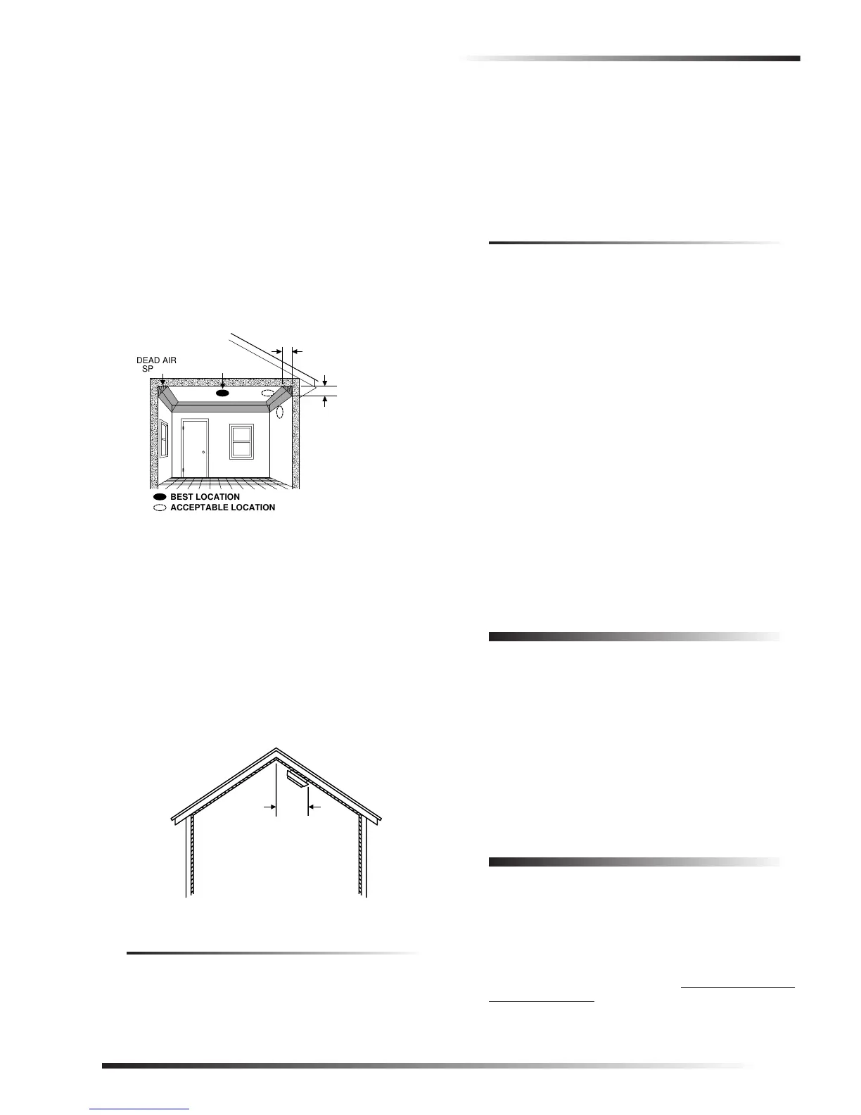
❑ Install smoke alarms on the ceiling as close to the cen-
ter of the room as possible. If this is not practical,
install it on the ceiling no closer than 4 inches (10 cm)
from any wall or corner (see figure 6).
❑ If ceiling mounting is not practical, install on an inside
wall between 4 and 6 inches (10 and 15 cm) from the
ceiling (see figure 6).
❑ Put smoke alarms at both ends of a bedroom hallway if
the hallway is more than 30 feet (9 meters) long. Large
rooms over 900 square feet require more than a single
sensor.
Figure 6.Smoke alarm mounting locations
❑ Areas with rough ceilings or short, transom-type walls
coming down from the ceiling require additional smoke
alarms.
❑ Install second-floor smoke alarms on the ceiling at the
top of the first-to-second floor stairwell. Be sure no
door or other obstruction blocks the path of smoke to
the unit.
❑ In rooms with sloped, peaked, or gabled ceilings,
install smoke alarms 3 feet (0.9 meter) measured down
on the slant from the highest point of the ceiling (see
figure 7).
Figure 7.Sloped, peaked, or gabled ceilings
Limitations
All alarms are subject to possible compromise or failure-to-
warn for a variety of reasons, for example:
❑ Smoke alarms cannot detect smoke in chimneys, walls,
roofs, or smoke blocked by a closed door.
❑ Alarms may not detect smoke on other levels of the
building.
❑ Alarms may not warn in time when fires are caused by
smoking in bed, explosions, improper storage of flam-
mables, overloaded electrical circuits, or other hazard-
ous conditions.
Do Not Install Smoke Alarms in the
Following Locations:
❑ In or near areas where combustion particles are nor-
mally present such as kitchens; in garages where there
are particles of combustion in vehicle exhausts; near
furnaces, hot water heaters, or gas space heaters.
❑ On the ceiling in rooms next to kitchens where there is
no transom between the kitchen and these rooms.
❑ In damp or very humid areas, or next to bathrooms with
showers. Install sensors at least 5 feet (1.5 meters)
away from bathrooms.
❑ In very cold or very hot areas.
❑ In dusty, dirty, or insect-infested areas.
❑ Near fresh air inlets or returns or excessively drafty
areas. Air conditioners, heaters, fans, and fresh air
intakes and returns can drive smoke away from smoke
alarms.
❑ In dead air spaces at the top of a peaked ceiling or wall/
ceiling intersect. Dead air may prevent smoke from
reaching a smoke alarm.
❑ Near fluorescent light fixtures. Install smoke alarms at
least 10 feet (3 meters) away from fluorescent light
fixtures.
Mounting
The mounting bracket must be separated from the unit
before you begin.
To mount the smoke alarm:
1. Secure the mounting bracket directly onto wood sur-
faces using No. 8, 1½ inch wood screws. If mounting
onto plaster or dry wall, use appropriate anchors.
2. Align the arrows on the mounting bracket with the
raised marks on the smoke alarm. Turn the smoke
alarm clockwise until it locks in place.
Testing
Test each smoke alarm every week to verify that its siren
and signal integrity are adequate. Refer to the specific panel
installation instructions for system response and sensor
testing.
To test the smoke alarm:
1. Put the panel in sensor test mode. Although not neces-
sary for this model, it is a good practice to maintain.
Refer to the specific panel installation instructions for
details.
,,,,,,,
,,,,,,,
,,,,,,,
,,,,,,,
,,,,,,,
,,,,,,,
BEST LOCATION
ACCEPTABLE LOCATION
DEAD AIR
SPACE
BEST IN CENTER
OF CEILING
NO CLOSER THAN 4
"
(10 cm)
FROM SIDE WALL
MOUNT ON WALL
AT LEAST 4
"
(10 cm)
FROM CEILING
NO MORE
THAN 6
"
(15 cm)
FROM CEILING
HORIZONTAL
DISTANCE
FROM PEAK
3 FEET
(.9M)