D400-18-00 1 I56-494-10R
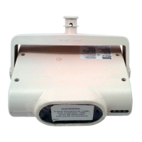
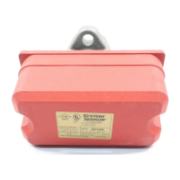
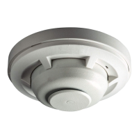
6424 Projected Beam Type
Smoke Detector
INSTALLATION AND MAINTENANCE INSTRUCTIONS
A Division of Pittway
3825 Ohio Avenue, St. Charles, Illinois 60174
1-800-SENSOR2, FAX: 630-377-6495
Specifications
General
Range: 30 to 330 Feet
Sensitivity: 30% ± 5% Total Obscuration, or
55% ± 5% Total Obscuration
Response Time: Alarm: 15 Seconds Max.
Trouble: 15 Seconds Max.
Trouble Condition: 95% or More Obscuration
Improper Initial Alignment
Self-compensation limit reached (service needed)
Test/Reset Features: Obscuration Filters (ALARM/NO ALARM)
Local Alarm Reset Switch
Remote Test and Reset Switch Capability
(compatible with RTS451 Test Station with Magnet)
Indicators: Alarm: Remote Output, Local LED (red)
Trouble: Remote Output, Local LED (yellow)
Normal Operation: Local LED (flashing green)
Alignment Aid: LED Bar Graph (4 red LEDs)
Relays: Alarm; Trouble
Environmental
Temperature: –30°C to 55°C (–22°F to 131°F)
Humidity: 10% to 93% RH Noncondensing
Mechanical
Weight: Receiver: 1.5 lbs (663 g)
Transmitter: 1.3 lbs (598 g)
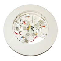
Mounting: Ceiling or Wall, Separate Mounting Brackets Provided
Wiring: Plug with Attached Cable
Adjustment Angle: Ceiling: ± 30° Horizontal/60° Vertical
Wall: ± 90° Horizontal/60° Vertical
Electrical (Receiver)
Voltage: 20 to 32 VDC
Maximum Ripple Voltage: 6.0 volts (Peak-to-peak)
Current (24 VDC): Avg. Standby: 10mA Max.
Avg. Alarm: 28.4mA Max.
Avg.Trouble: 27.1mA Max.
Start-up Surge: 19mA Max.
Relay Contacts: .5A at 30 VAC/DC
Reset Time: .6 Seconds Max.
Start-up Time (after 5 min. reset): 1 Minute Maximum
Power Loss: Retain Memory for 5 Minute Minimum
Electrical (Transmitter)
Voltage: 18.8 to 32 VDC
Maximum Ripple Voltage: 5.6 volts (Peak-to-Peak)
Avg. Current (24 VDC): 10mA Max.