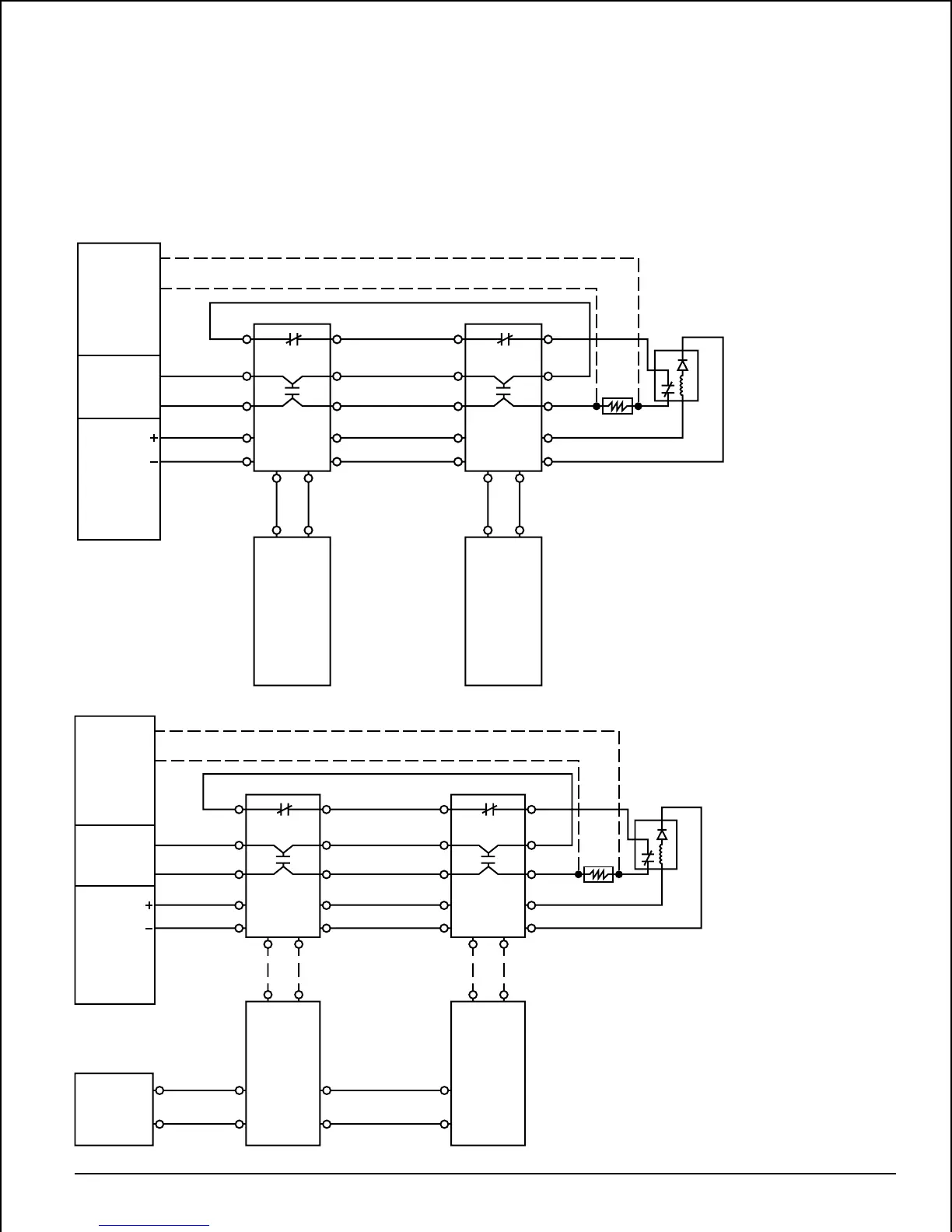
wires. Figure 8 shows an alternative wiring configuration in
which the transmitter receives its power from a remote
power source. Temporary wiring can be installed for the
communication needed for transmitter alignment aid. If the
remote power configuration is used, the remote power
source must comply with all codes and directives of the
Authority Having Jurisdiction. NOTE: The transmitter
CLASS A
RETURN LOOP
INITIATING
LOOP
POWER
TO
DETECTORS
LISTED PANEL
TRANSMITTER
BLUE GREEN
ORANGE
GREEN
BLACK
RED-WHITE
STRIPE
WHITE
WHITE-BLACK
STRIPE
GRAY
VIOLET
WHITE-VIOLET
STRIPE
BROWN
WHITE-
YELLOW
STRIPE
WHITE-RED
STRIPE
TRANSMITTER
ORANGE
GREEN
BLACK
RED-WHITE
STRIPE
WHITE
WHITE-BLACK
STRIPE
GRAY
VIOLET
WHITE-
VIOLET
STRIPE
BROWN
WHITE-
YELLOW
STRIPE
WHITE-
RED
STRIPE
RECEIVER RECEIVER
EOL
RESISTOR
LISTED
EOL POWER
SUPERVISION
RELAY MODULE
(SHOWN ENERGIZED)
BLUE GREEN
NOTE: FOR PROPER
SUPERVISION, AN
EOL RELAY MUST
BE USED.
Figure 7. Transmitter permanently wired to receiver:
A78-2043-00
CLASS A
RETURN LOOP
INITIATING
LOOP
POWER
TO
DETECTORS
LISTED PANEL
LISTED
REMOTE
POWER
SOURCE
POWER
INPUTS TO
TRANSMITTER ARE
NONPOLAR
TRANSMITTER
BLUE
GREEN
WHITE
BROWN
BLACK RED
ORANGE
GREEN
BLACK
RED-WHITE
STRIPE
WHITE
WHITE-BLACK
STRIPE
GRAY
VIOLET
WHITE-VIOLET
STRIPE
BROWN
WHITE-
YELLOW
STRIPE
WHITE-RED
STRIPE
TRANSMITTER
BLUE
GREEN
BLACK RED
ORANGE
GREEN
BLACK
RED-WHITE
STRIPE
WHITE
WHITE-BLACK
STRIPE
GRAY
VIOLET
WHITE-
VIOLET
STRIPE
BROWN
WHITE-
YELLOW
STRIPE
WHITE-
RED
STRIPE
RECEIVER RECEIVER
EOL
RESISTOR
LISTED
EOL POWER
SUPERVISION
RELAY MODULE
(SHOWN ENERGIZED)
OPTIONAL TEMPORARY WIRING FOR
TRANSMITTER ALIGNMENT AID.
NOTE: FOR PROPER
SUPERVISION, AN
EOL RELAY MUST
BE USED.
Figure 8. Transmitter powered separately:
A78-2042-00
D400-18-00 5 I56-494-10R
should be permanently wired to the receiver (Figure 7)
whenever possible to allow the alignment LEDs on the
transmitter to be used during the alignment procedure.
Figure 9 shows the remote outputs for trouble and alarm,
while Figure 10 shows the connection necessary for using
the remote test station (RTS451 or RTS451KEY).