[6.1] Smoke Entry Tests
[6.1.1] Air Flow
To verify sufficient sampling of ducted air, use a manometer
to measure the differential pressure created from air flow
across the sampling tubes. The pressure should measure
no less than 0.01 inches of water and no greater than 1.20
inches of water.
[6.1.2] Smoke Response
To determine if smoke is capable of entering the sensing
chamber, visually identify any obstructions. Plug the ex-
haust and inlet tube holes to prevent ducted air from car-
rying smoke away from the detector head, then blow smoke
such as cigarette, cotton wick, or punk directly at the head
to cause an alarm. REMOVE THE PLUGS AFTER TESTING
OR THE DETECTOR WILL NOT FUNCTION PROPERLY.
[6.1.3] Filter Replacement
The filters do not substantially affect smoke behavior
even when they are up to 90% clogged. Quarterly visual
inspection is usually often enough to determine if filters
should be replace because only a high percentage of con-
tamination affects duct detector performance.
[6.2] Standby, Alarm, And Sensitivity Tests
[6.2.1] Standby And Trouble
Standby- Check for the presence of the blinking red LEDs
(blinks about every 10 seconds) through the
transparent housing cover. If the APA451 ac-
cessory is used, its green Power LED should be
illuminated continuously.
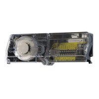
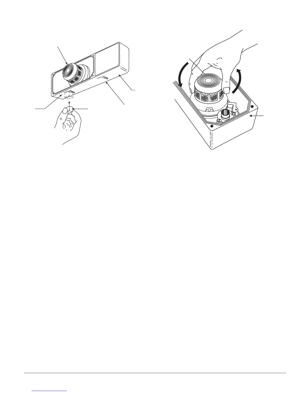
Figure 10. Testing detector alarm: Figure 11. Detector head removal:
TEST
LOCATOR
TEST
MAGNET
PAINTED SIDE
TOWARD HOUSING
DUCT
HOUSING
DETECTOR
HEAD
RESET
LOCATOR
TWIST
COUNTERCLOCKWISE
TO REMOVE
DUCT
HOUSING
TWIST
CLOCKWISE
TO INSTALL
DETECTOR
HEAD
H0250-00 H0251-00
Trouble- If the detector LEDs do not blink or if the APA451
Power LED is not illuminated, the detector lacks
power (check wiring, panel, or power supply),
the head is missing (install), or the unit is defec-
tive (return for repair).
Test- The trouble condition can be caused
intentionally to verify correct operation of the
system. Remove power to the unit, remove the
detector head (see Figure 11), or place the M02-
04-00 magnet into the Reset locator, as shown in
Figure 10. These actions should cause a trouble
condition locally and at the system control
panel.
[6.2.2] Alarm Tests
[6.2.2.1] M02-04-00 Magnet Test
1. Place the painted surface of the magnet into the Test
locator molded into the side of the housing (see Figure
10).
2. The red alarm LEDs on the detector should latch on,
as should any accessories (PA400, RA400Z, RTS451,
APA451). Verify auxiliary functions (such as fan shut-
down) and system control panel alarm status.
3. Place the painted surface of the magnet into the Reset
locator molded into the side of the housing (see Figure
10). This should clear the latched alarm condition at the
detector. If a system control panel is used, the panel may
also require resetting.
[6.2.2.2] RTS451/RTS451KEY Remote Test Station
The RTS451/RTS451KEY Remote Test Station facilitates test
of the alarm capability of the duct detector as indicated in
D400-13-00 9 I56-555-09R