conditions will impair the proper operation of the detector
and must be avoided.
Approved Accessories
The following accessories can be purchased separately for
use with this beam detector.
BEAMLRK
The BEAMLRK allows System Sensor reflected beam detec-
tors to be installed at separations between 230 and 328 feet
(70 to 100 meters). At these distances, four 8″×8″ reflectors
must be used to provide enough reflected infrared light.
This kit includes 3 additional reflectors with new test
scale legends. The reflector included with the transmitter/
receiver unit is the fourth reflector to be used. This kit is
not compatible with the multi-mount kit (BEAMMMK).
BEAMMMK
The BEAMMMK allows System Sensor reflected beam detec-
tors and reflectors to be mounted to either a vertical wall or
the ceiling. The kit allows for additional alignment range in
cases where the detector and reflector cannot be mounted
within 10° of each other. The kit includes the hardware
necessary to mount either a single transmitter/receiver unit
or a single reflector. (To mount the transmitter/receiver the
surface mount kit, BEAMSMK, must also be used). If the
transmitter/receiver and the reflector require additional
alignment range two kits are required. The kit is not com-
patible with the long-range reflector kit (BEAMLRK).
BEAMSMK
The BEAMSMK allows System Sensor reflected beam detec-
tors to be mounted when surface wiring is used. This kit
must be used when mounting the transmitter/receiver unit
with the multi-mount kit (BEAMMMK).
BEAMHK
The BEAMHK allows the transmitter/receiver unit to oper-
ate in environments prone to the formation of condensa-
tion. Condensation forming on the beam detector unit
may result in trouble or false alarm conditions. BEAMHK
will lessen the likelihood of condensation by maintaining
the unit at a temperature that is slightly higher than the
surrounding air. Please refer to the BEAMHK installation
manual for operation instructions.
BEAMHKR
The BEAMHKR allows the reflector to operate in environ-
ments prone to the formation of condensation. Condensation
forming on the reflector may result in trouble or false alarm
conditions. BEAMHKR will lessen the likelihood of conden-
sation by maintaining the reflector at a temperature that is
slightly higher than surrounding air. The kit requires a 24V
power supply. When used with the long-range reflector kit
(BEAMLRK), it is necessary to purchase and install four
BEAMHKR kits. Please refer to the BEAMHKR installation
manual for operation instructions.
RTS451/KEY
The remote test accessory, RTS451/KEY allows for the
beam detector to be tested remotely. The test accessory
provides test and reset functions and green and red LED’s
that mimic the LED’s on the detector.
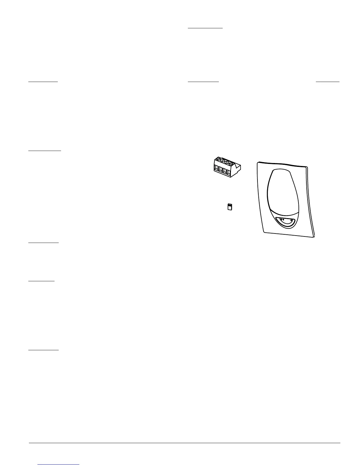
Parts List
Description Quantity
Transmitter/Receiver Unit . . . . . . . . . . . . . . . . . . . .1
Paintable Trim Ring . . . . . . . . . . . . . . . . . . . . . . . . .1
Reflector . . . . . . . . . . . . . . . . . . . . . . . . . . . . . . . . .1
Plug-in Terminal Blocks . . . . . . . . . . . . . . . . . . . . . .3
Isolator Shunts . . . . . . . . . . . . . . . . . . . . . . . . . . . .2
Instruction Manual . . . . . . . . . . . . . . . . . . . . . . . . .1
Orange Sticky Paper . . . . . . . . . . . . . . . . . . . . . . . . .1
Parts Diagram (not to scale)
C0306-00
Detector Placement
This section of the manual discusses the placement of pro-
jected beam detectors. Though this information is based
upon industry expertise, it is intended to be used only as
a technical guide. Always comply with the requirements of
applicable codes and standards such as, NFPA 72, National
Fire Alarm Code, as well as directives of the Authority
Having Jurisdiction (AHJ).
Projected beam detectors are usually located with their
beams parallel to the ceiling. However, they can be mount-
ed vertically or at any angle to protect the area involved.
Since beam detectors sense the smoke buildup over a dis-
tance, they are ideal for locations with high ceilings. They
can also be mounted on a wall or ceiling below the level
of a spot type detector, reducing the effects of air stratifica-
tion. Some typical locations would include large areas with
high ceilings such as atriums, warehouses, and factories.
NOTE: Projected beam smoke detectors should always
be mounted to stable mounting surfaces. See the
MOUNTING LOCATION section for details.
N200-25-00 3 I56-2424-04R
Terminal Block
Paintable
Trim Ring
Isolator Shunt