6
GB IE
Safety Information
Installation, electrical connection and commissioning are only
to be carried out by authorised personnel and in accordance
with the requirements and demands of the high-tension
current regulations. Installation carried out according to EN
60079-14 is considered to comply with the demands of the
high voltage directive’s requirements. The fan should be
installed and protected to secure against spark generation
caused by foreign objects coming in contact with the impeller.
Rust particles are not to be found in the air stream. The
transported air should not corrode the fan’s casing, impeller
or axis. (aluminium and steel). If the fan isn’t installed in a
duct system; a protection grid should be installed. No moving
parts should be accessible after installation (EN 294).
Electrical connection should be made according to the wiring
diagram in the terminal box, markings on terminal blocks or
on cable. Protection earth (PE) should always be connected.
(If there’s risk for static electricity a separate earthing should
be attached to the casing of the fan). The fans are allowed
for use in explosive environments ( Ex eq II T3 for I-phase
and Ex e II T3 for 3-phase) and for transport of gases, but
may not be connected to a flue-gas ducts. Fan-type DVEX
must be installed with monitoring equipment of type U-
EK230E, monitoring equipment should be labelled
“PTB03ATEX3045”. The monitoring equipment is fitted with a
manual reset and an indicator light that is lit when the motor
has been switched off, the equipment should be placed
outside of the danger zone.
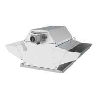
If the DVEX fan is equipped with tilting device, it may not be
opened or tilted when explosive atmosphere is present. In
order to prevent the fan from tilting down accidentally, it must
be secured by means of a screw (M6x10). (2 screws from
assembly 450 on!). In addition to this, the folded brackets are
secured by means of one screw (M8x16) each, which also
must be used to secure the fan when it´s open in such a way
that the fan is prevented from tilting down accidentally. Fig, 4
Close the fan with a cautious hand, do not drop it.
The motor switch that should be adjusted so that it protects
the motors from overload and releases within 15 sec if
impellers are obstructed. In order to determine the release
time for the motor protection there should be a release curve
that shows the release time for the motor protection as a
function of the preoscillation current condition (start-up
current status) (IA/IN) for 2,9 < IA/IN < 8 with ambient
temperature of 20°C. The motor protection’s release time is
not allowed to deviate more than 20 % from release curve.
To limit the fan motor’s current to the values given in table 1
the static pressure must be adjusted by chocking the fan.
The fans must not be installed outdoors, (with exception
DVEX). Safety accessories (i.e. motor protection, safety
grille) may not be dismounted, short cut or disconnected.
Before maintenance, service or repair make sure that Power
supply is interrupted (all-pole circuit breaker) and that the
impellers have come to a complete stop.
CAUTION The fans can have sharp edges and corners
which may cause injuries. Be careful when opening the fans
service-hatches (swing-out), the fan and motor assembled on
the hatch is relatively heavy.
Transportation and Storage
All fans are packaged at the factory to withstand normal
transport handling. When handling the goods use suitable
lifting equipment in order to avoid damage to fans and
personnel. Note! Do not lift the fans by the mains cable,
connection box, and impeller or inlet cone. Avoid blows and
shock loads. Store the fans in a dry place protected from
weather and dirt until final installation. Avoid excessive
storage periods (we recommend a one year max.). Before
installing the fan, check motor bearings for any noise.
Installation
Always refer to Safety information above before
installation.
The installation demands that a classification of the
hazardous area has been made according to valid
prescriptions (Sweden applies SRVFS 2004:7) and
classification standards (European countries connected to
CENELEC apply EN 60079-10).
Particles of rust are not to be found in the air stream.
Monitoring equipment should be labelled “PTB03ATEX3045”.
CAUTION Do not use metal compression gland fittings with
plastic terminal boxes. Use a dummy plug seal for the
compression gland fitting as well, to ensure that the
requirements for capsule class IP 54 according to IEC 529
could be fulfilled. Ambient temperature and temperature for
transported air should be in the range -20°C till +40°C. Mount
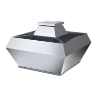
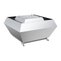
the fan according to the airflow (see arrow on unit). The fan
must be installed so that vibrations are not transmitted to
duct systems or frame of building. (Suitable accessories like
clamps and flanges are available). Make sure the fan is firmly
fixed and stable. The fan can be mounted in any direction
unless stated otherwise. The fans must be assembled so that
service and maintenance can be carried out easily and
safely. Disturbing noise can be avoided by installing silencers
(available accessory). The fans are meant for continuous use
within the temperature range stated.
Duct installations should be carried out so that capsule class
IP 20 (mesh width less than 12mm) is fulfilled on inlet side
and IP 10 (mesh width less than 50mm) on outlet side. The
parts that are responsible for the IP protection should be
satisfactory designed regarding strength and material. The
cable end from the fan should be installed so that it is
mechanically protected and suited for use in the surrounding
environment. Mains supply for EX-fans must be fixed. In case
of external grounding of the chassis, see Fig. 1 page 2. Earth
wire (b) should be pinned between 2 pieces of tin plates (a).
Operation
Always refer to Safety information above before initial
operation.
When putting into operation, check:
- That measured data isn’t allowed to exceed the value on
the fan’s nameplate. Rated current can be decreased
when fan is set under pressure. Connection data
corresponds to the specifications on the nameplate:
Maximum voltage +6%, -10%, according to IEC 38. Rated
current must not be exceeded at rated voltage. When
speed regulating fans, by reducing the voltage, the fans
should be operated with a rated voltage from 15% up to
100% of their rated voltage. The minimum static pressure
drop must not be exceeded (Observe table 1). The fans
may not be frequency controlled.
- That the motor protection is working.
- That the rotating direction of the fan corresponds to the
arrow
- That the motor is running smoothly (no abnormal noise).
- That no moving parts are touching the chassis or protection
grilles.
- That no extensive on and off regulation is in use. The
fans are intended for continuous operation.
 Loading...