Installation |
11
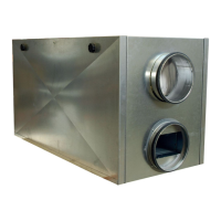
8.1.1 DVC-P measuring tubes
The following illustrations show the schematic installation of the measuring tubes.
Size
190–225
Size
315–710
A
Measuring tubes
B Duct system
Controller input
-
Duct system
+
Atmosphere
8.2 Assembly/Disassembly impeller — Internal rotor motor
If an external rotor motor is used, the motor and impeller can`t be seperated.
Damage to the motor and impeller.
The ball bearing of the motor and the balanced impeller may be damaged by forceful impacts.
♦ Attach the impeller and/or the shaft extension to the shaft or the rotor without forceful impacts.
♦ Do not separate the impeller and the hub. They were balanced as one unit by Systemair.
Note:
The hub can be heated for easier assembly and disassembly, for example with a hot-air blower.
• Precondition for assembly: the wedge is in the intended groove.
• Tools: hexagon socket wrench and suitable tool for removal, torque wrench for the taper clamping bush.
1 Motor
2
Motor shaft
3
Sleeve (not available at every fan)
4
Shaft extension (not available at every fan)
5
Hexagon socket screw
6
Impeller
7
Steel hub
8
Aluminium hub
The hub is shown without impeller due to better lucidity.
| 006