EC-Vent
Demand control for up to 5 external sensors, 2 fans, damp-
ers, heaters and coolers.
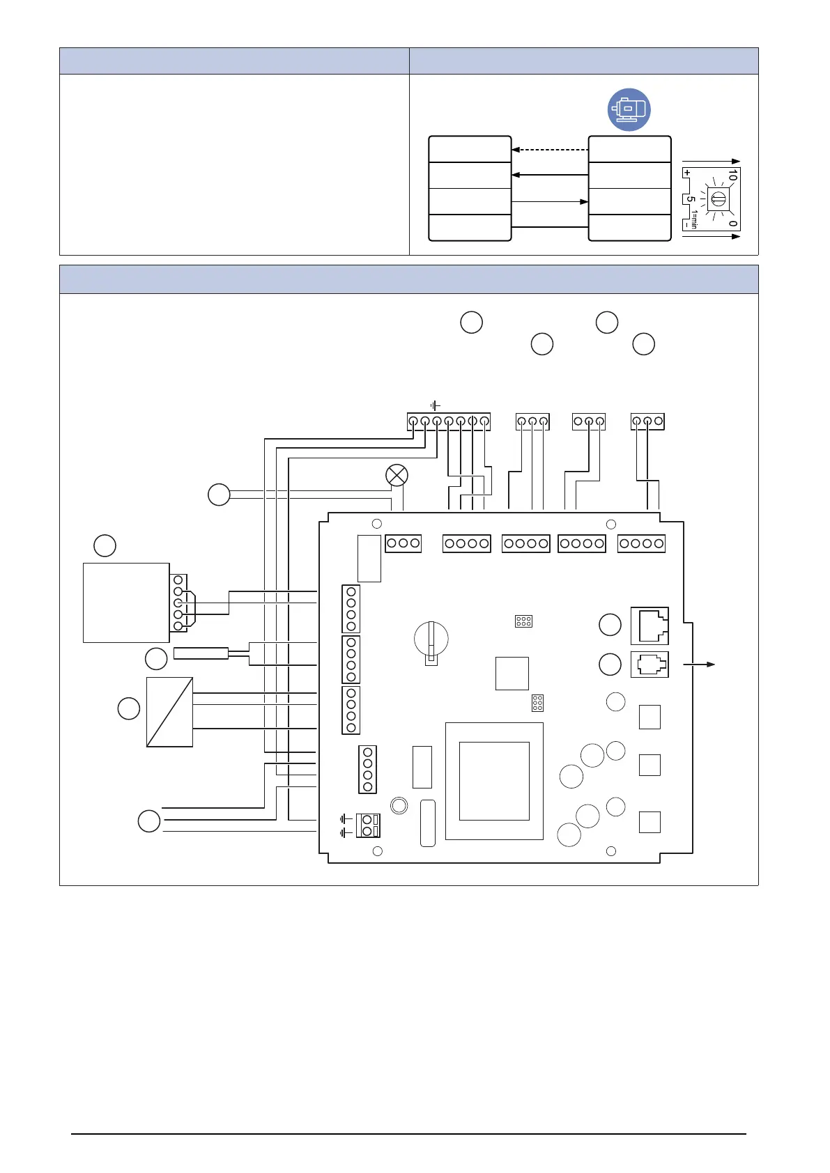
The EC vent system has 2 units. The control board (CB) and
the room unit (RU). Connect the fan to the control board and
remove the internal potentiometer.
EC-Vent
IN/RPM
PWM
IN/10V
OUT/PWN
GND
TACH
optional
+10V
0...10V/PWM
GND
Control Board (CB)
W -
Y +0-10V
Br + 24VDC
NC
C
NO
GND
+24VDC
E
C
B
D
A
N
L
1
(tach output)
2 (GND)
3 (PWM)
4 (+10VDC)
2 (+24VDC)
3 (0-10V)
1 (GND)
+ DC MAX 24V
I max 50mA
5 (GND)
6 (0-10V)
7
F
G
H
I
CMN
NC
NO
MODBUS INTERNAL
GND
IN/10V
OUT/PWM
IN/RPM
24V
D
A
GND
24V
D
A
GND
24V
D
A
GND
RU
DEBUG
USB
J
K
ALARM FAN OUT3 OUT2 OUT1
GND
A/D
PT1000
24V
GND
A/D
PT1000
24V
GND
A/D
PT1000
24V
N out
N in
L out
L in
IN3 IN2 IN2
27
 Loading...