A. Mains supply, 230 V 1~AC (10 A)
B. Analogue sensor (e.g. pressure sensor)
C. Analogue sensor (e.g. pressure sensor type PT1000)
D. Digital sensor (e.g. IR presence detector)
E. Alarm output (max 24 V AC/DC, max 500 mA Cosφ >0.95)
F. Output to EC fan
G. Output to analogue actuator with 24 V DC supply
H. Output to digital signal (DC Max 24 V, 1 max 50 mA)
I. Output to analogue actuator (e.g. heat regulator)
J. Connection to Modbus
K. Connection to room unit (RU)
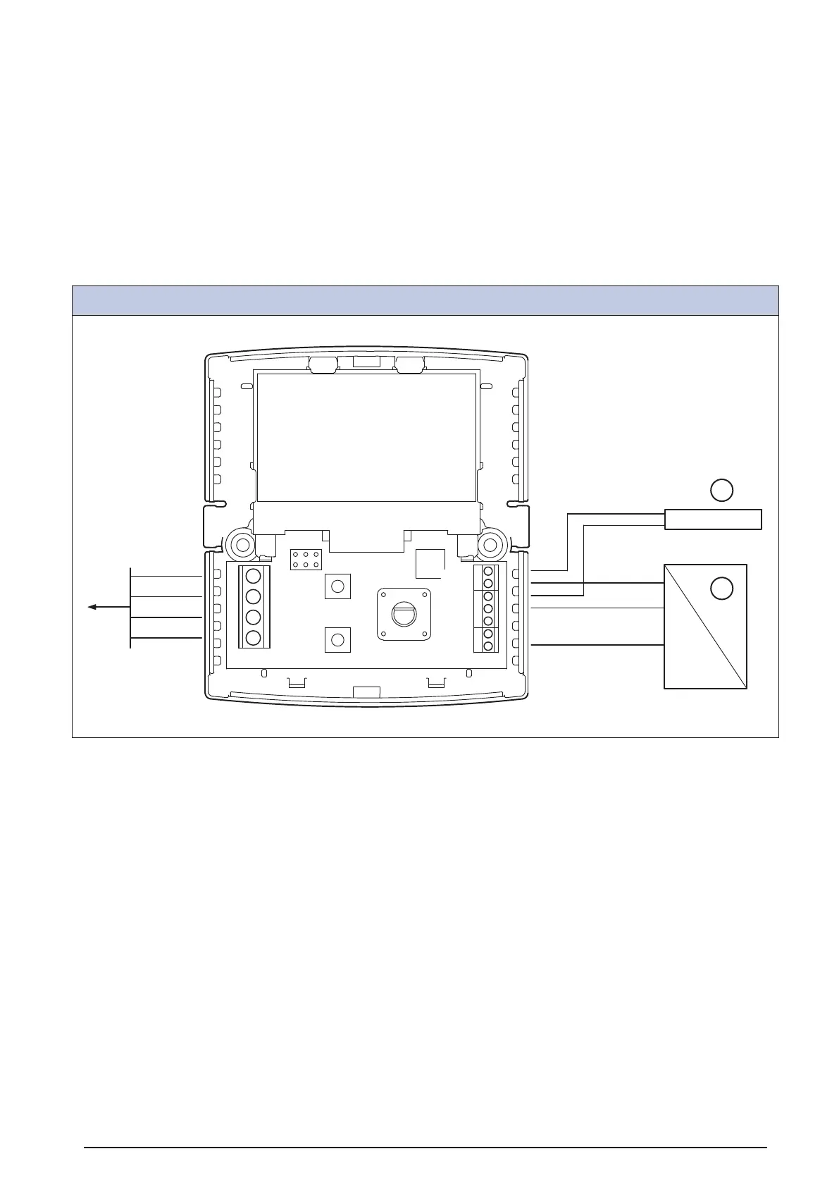
Room Unit (RU)
Br + 24VDC
Y +0-10V
Gr-
Bl (GND)
R+ 24VDC
Y +0-10V
W -
CB
A
B
GND
24V
REF
T1
I2
I1
24V
C
B
A. CB = Control Board
B. Analogue sensor (e.g. pressure sensor)
C. Analogue sensor (e.g. pressure sensor type PT1000)
28
 Loading...