Electrical connections |
27
• Alarms— detailed description of all alarms.
• Troubleshooting— information about all different possible malfunctions.
8 Electrical connections
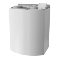
The SAVE VTR 500 is wired internally from factory.
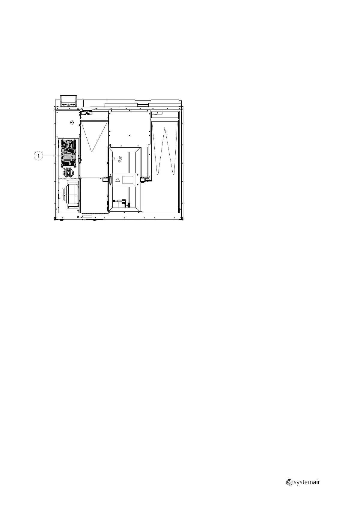
The electrical connection box can be found on the supply air outlet side of the unit behind a cover plate. The print card
can easily be taken out from the unit.
Fig. 7 Print card position
8.1 Main board layout
The SAVE VTR 500 is equipped with built-in regulation and internal wiring.
The figure shows the main circuit board. See wiring diagram for more information.
211477 | A001
 Loading...