Accessories
|
41
ZTR 15-0,6 valve 3-way — 6573
ZTR 15-1,0 valve 3-way — 6572
• Duct sensor -30-70C (SAT) — 211524
• Surface sensor -30-150C (FPT) — 211523
Installation and connection
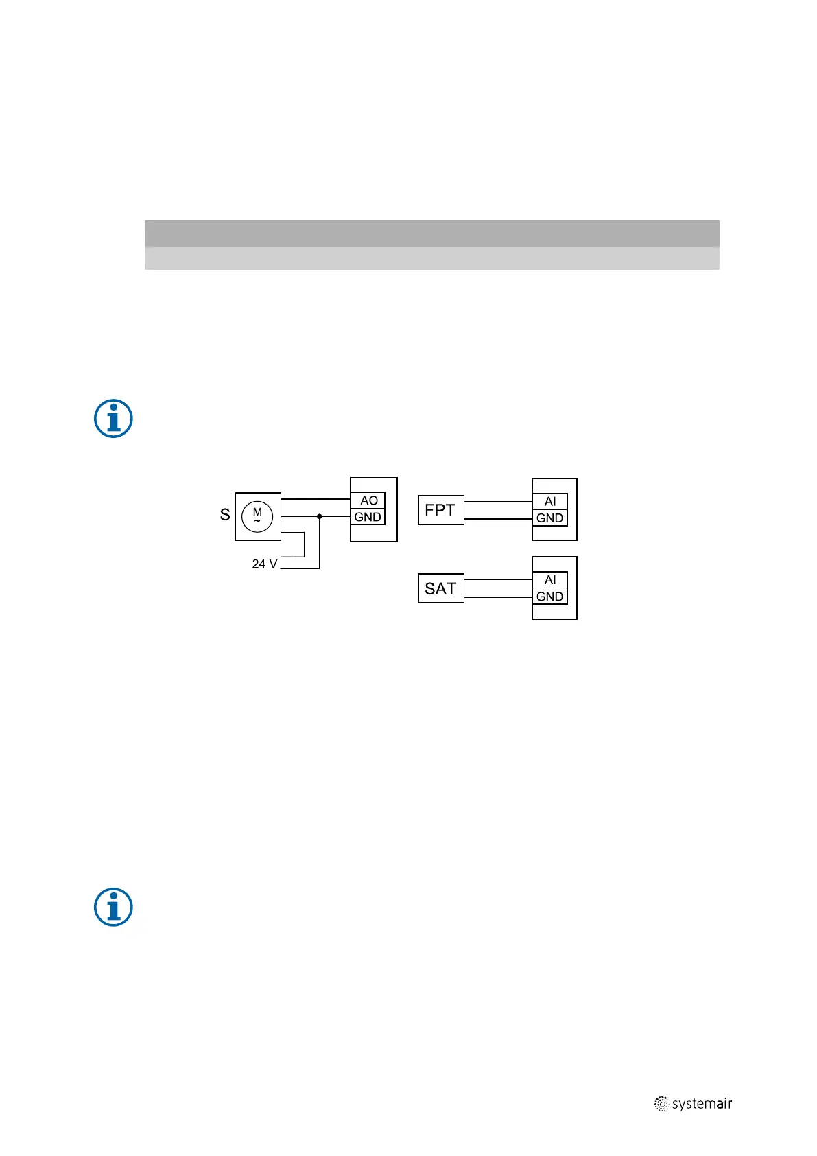
1. Install water heater in the duct. Connect pipes, 2/3–way valve and actuator.
Important
Do NOT use 24V DC power output from the connection board for valve actuator.
2. Connect actuator (S) to any free analog output.
3. The frost protection sensor (FPT) should be strapped on a surface on the return water pipe. Connect FPT sensor to
any free analog input.
4. Internal supply air temperature sensor (SAT, default connection AI2 on the main circuit board) must be replaced by a
duct temperature sensor which can be acquired as an accessory. A duct temperature sensor must be installed in the
duct after water heater: Connect duct temperature sensor in a place of internal supply air temperature sensor (AI2).
Note:
A duct temperature sensor can be connected to analog inputs 6–7 on the connection board for better
access when the internal supply air temperature sensor is disabled in the control panel. Then temperature
sensor has to be re-configured as universal analog input.
Fig. 15 Water heater connections
Configuration
1. Go to Service menu
2. Enter password (default 1111)
3. Activate the actuator. Go to Components menu, select Heater menu and select type as Water. Choose actuator
voltage type. Do advanced settings if necessary.
4. Configure connection of the water heater. Go to Service menu. Select Output menu. In next menu select ANALOG
tab. Select the analog output to which the water heater is connected. Example if it is connected to AO3 on the con-
nection board, then select ANALOG OUTPUT 3 and select Y1 Heating from the output type list.
5. Configure frost protection sensor (FPT). Go back to Input menu. Select ANALOG tab. Select the analog input to which
the frost protection sensor is connected. Example if it is connected to AI6 on the connection board, then select ANA-
LOG INPUT 6 and select Frost Protection Temperature Sensor (FPT) from the input type list.
6. Since a duct temperature sensor replaces internal supply air temperature sensor, it doesn’t need to be re-configured.
Note:
A duct temperature sensor can be connected to analog inputs 6–7 on the connection board for better
access when the internal supply air temperature sensor is disabled in the control panel. Then temperature
sensor has to be re-configured as universal analog input.
7. Water heater and its components are now configured.
211477 | A001
 Loading...